The effect of frequency in
welding thick-walled HFI pipes
Hendrik Loebbe
Introduction
The use of High Frequency
Inductive (HFI) welding is a highly productive process for the
manufacture of longitudinally welded pipes from hot‑rolled strip.
Longitudinally welded HFI pipes are nowadays used in the most diverse
range of applications. Typical of such uses are, for example, pipelines
for the conveyance of liquid and gaseous hydrocarbons, potable and
utility water, brine, district heating systems, hollow sections and Oil
Country Tubular Goods (OCTG). Mannesmann Fuchs Rohr (Siegen and Hamm,
Germany) produces HFI pipes in O.D. 4”-20” (114.3-508.0 mm) with wall
thicknesses up to t = 0.81” (20.6 mm). Special requirements originating
from the offshore sector are thus also fulfilled via the use of
high‑quality grades of steel with large pipe‑wall thicknesses [1]. In
this sector, HFI pipes are increasingly coming into use in the offshore
sector, in competition with SAW and seamless pipes. Not least important
of all in this context is the trend toward the production of ever
thicker‑walled HFI pipes. The technological preconditions necessary for
this purpose, in terms of HFI welding technology, are discussed, with
attention to normative aspects, in the following essay, with prime
emphasis attended to the topic of "welding frequency".
The welding process
The welding process is the
central operation in the chain of production processes involved in the
manufacture of pipes from hot‑rolled wide strip. One can differentiate
essentially between fusion welding and pressure welding, with a number
of diverse process variants [2]. Fusion welding methods take the form of
the submerged‑arc and gas metal-arc welding processes for production of
longitudinally welded and spiral‑welded pipes. The pressure welding
processes include among others the low-frequency and the high‑frequency
welding, the latter being the subject of this essay. There are in the
relevant literature no generally applicable differentiations based, in
particular, on physical principles and/or phenomena for definition of
the high‑frequency technology frequency range, particularly in the case
of welding. Minimum frequency values for HF welding can be found in
international product standards and specifications for pipes, such as EN
10208-2, ISO 3183-2, ISO 3183-3 and API Specification 5L
[3],[4],[5],[6]. Here, a frequency of f ≥ 100 kHz is required for HF‑welded
pipes, irrespective of all other boundary conditions (API Spec. 5L, PSL 2
only). No upper frequency limit is stated, however. Elsewhere, the term
"high‑frequency" is defined, for example, as the "f = 50 to 10,000 kHz"
or "f = 10 to 5,000 kHz" frequency range [7],[8].
It is possible, in
principle, to differentiate in the context of HF welding processes
between conductive and inductive transfer of energy. In the case of
conductive technology, input of energy is accomplished with copper
contacts via the surface of the pipe, with the resultant possibility of
strikes and burns on this surface. In inductive systems energy transfer
is accomplished without contact. In both cases, it must essentially be
assured that the necessary "skin effect" is generated. Utilizable
minimum frequencies were in the past the result primarily of the
thermionic valve‑based generator technology and the power thus
available. The advance of transistor technology permits the use of lower
frequencies combined with higher power, particularly in the case of the
HFI process. This is useful, in particular, for welding of thick‑walled
HFI pipes which is one factor permitting the increased use of such
longitudinally welded pipes in offshore application. Anyway, the minimum
frequency in this context is 100 kHz, in order to fulfill the
requirements of the various standards and specifications.
Physical effects
In both conductive and
inductive HF welding, the principle is based on the fact that a current
flows on the pipe surface and the band edges (Fig.
1). This high‑frequency current
flows on the surface of the pipe via the edges of the strip to the
welding point at which the melted strip edges are forced together and
welded.
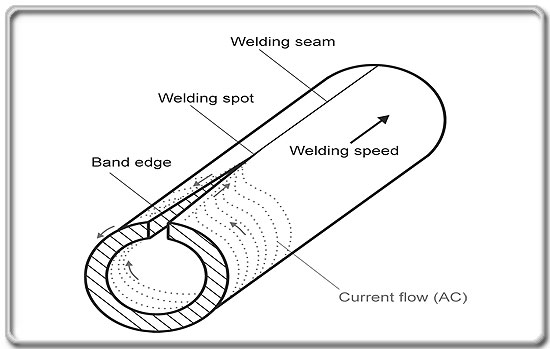
Fig. SEQ Fig. \* ARABIC
1: Current flow on the surface of the pipe
The precondition for the
achievement of the flow of current on the pipe surface and on the edges
of the strip is the so‑called "skin effect" (Fig.
2). A further increase in current
density on the strip edges results in the "proximity effect". The
current's penetration depth is determined essentially by the temperature
of the material relative to the Curie temperature.
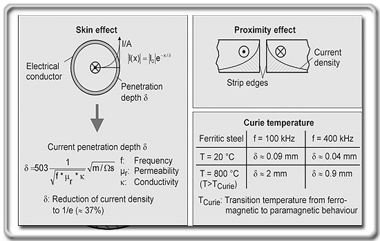
Fig. SEQ Fig. \* ARABIC
2: Basic principles [9],[10],[11]
The skin effect causes on
the surface of a conductor an increase in current density dependent on
frequency. Current density drops in the form of an e‑function as
distance from the conductor edge increases. Reduction of current density
to 1/e (approx. 37 %) is defined as current penetration depth. The
influencing factors are material‑dependent characteristics and
frequency. Frequency thus provides a method of controlling penetration
depth and temperature increase in the boundary zone of the band edges.
It must be noted that influence is relative to the square root and that
a quadrupling of frequency thus results in a halving of penetration
depth. In the case of HFI welding, the skin effect results in the
current flowing only on the pipe surface and in heating up of the strip
edges to welding temperature at the welding point.
The proximity effect also
causes a further increase in current density in the strip edge zone.
This effect is based on the fact that the charges, with currents flowing
in opposite directions, attract each other.
The third aspect with a
significant influence on the profile of temperature of the strip edge is
the excess of Curie temperature. This occurs, in accordance with the
iron‑carbon diagram, at T = 769 °C [2]. Ferritic steels exhibit
ferromagnetic behaviour below this temperature, and paramagnetic
behaviour above it. This has a significant effect on the current's
penetration depth. Penetration depth will rise, for example, around
22‑fold if the temperature at the strip edge rises above the Curie
temperature during HF welding.
The dependence of
temperature profile on frequency
The heating profile at the
edges of the strip can be manipulated, inter alia, via the selection of
frequency. It must be technologically assured that the skin effect is
achieved. The penetration depth of the heat‑affected zone (HAZ),
particularly at the center of the strip, is generally increased as
frequency decreases. The irregular configuration of the heat‑affected
zone, in the form of an hour‑glass, is lessened. This results in the
steel's welding temperature also being reached with processing certainty
at the center of the strip (Fig. 3,
Fig. 4). The
overheated corners of the strip edges possible at higher frequencies are
eliminated at lower ones, such as may be used in HFI process.
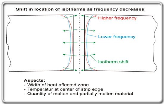
Fig. SEQ Fig. \* ARABIC
3: The effects of frequency on temperature profile in connection with
HFI welding

Fig. SEQ Fig. \* ARABIC
4: Heating profile at strip edges in production of thick-walled pipe
Only a few systematic
investigations of the influence of frequency on the process, on the one
hand, and on the technological properties of the pipe, on the other
hand, have been published. A number of these are discussed below.
The development of
transistor technology has made it possible to use frequencies below
f = 200 kHz for the purpose of HFI welding [12]. In the past, due to
valve‑based technology, the minimum frequency from a technological and
economic standpoint was, on a system‑engineering view, around
f = 250 kHz. Extremely fast MOSFET transistors have been in use in HFI
resonant circuits since the mid‑1980s; in addition, high‑current IGBT
transistors have increasingly become established in the welding‑systems
sector in around the last ten years, and thus permit frequencies down to
100 kHz for HFI welding [12],[13]. Both types of transistor are nowadays
used, depending on their strengths and the corresponding requirements.
The potential for technologically and economically rational use of
frequencies down to 100 kHz for HFI welding must, as already mentioned
above, also be viewed in close conjunction with the trend toward
production of ever thicker HFI pipe‑wall thicknesses.
Finite Element Method
(FEM) analysis studies have been performed into the influence of various
process parameters, and frequency, in particular, on the HFI welding
process [14],[15],[16]. The following influencing factors were examined
here: welding angles, distance of the welding point from the inductor,
resilient flexing of the strip edge, welding speed and welding
frequency. The reasons for performance of these published investigations
can be found in welding problems encountered in the production of pipes
with a wall thickness of t = 12.7 mm, which were attributed to a cold
strip center. It was ascertained that all the factors investigated
significantly influence the configuration of the heat profile in the
edge of the strip. As far as frequency is concerned, the frequency
100 kHz cause a much more uniform increase in temperature up into the
center of the strip edge than the frequency 300 kHz. The percentage of
melted material in the vicinity of the corners of the strip edge falls
significantly as frequency falls, thus reducing burn‑off of these
corners. It becomes apparent in the relevant investigations, however,
that the other parameters examined also have a significant influence on
the heat profile in the edge of the strip material and must therefore
also be used for description of the process. A factor of two in the case
of the angle of approach of the weld vee, for example, thus has a
greater influence than a factor of three for frequency.
In contrast to this, there
are also studies concerning the influence of frequency, the essential
criteria of which are the spread of the heat‑affected zone and thus
necessary power [17],[18]. These investigations are also unanimous in
stating that penetration depth in the f = 100 to 600 kHz range becomes
greater as frequency falls. The unbalanced conclusion of these authors,
failing to take account of other technological boundary conditions, is
in this case that higher frequencies are assumed to be more economical,
since a greater penetration depth would be a waste of energy, and that
higher power is therefore necessary. With respect to the complete
melting of the edges of the strip, this must be critically evaluated,
however. At lower frequencies in the case of HFI welding, heating up to
the center of the strip is assured with processing certainty even in the
case of greater wall thicknesses.
Practice also demonstrates
that the process as a whole, including the environment in which it takes
place, must also be studied, in addition to these physical principles.
If the process chain, including upstream and downstream facilities, is
thus examined, it will be necessary, for example, to analyze the
interaction of possible power input and welding speed. The principal
objective, that of producing, cost‑effectively, pipes which meet the
specification, must continuously be borne in mind during all such
deliberations, however.
The use of
adjustable‑frequency HF generators is recommended for large
wall‑thickness/diameter ratios [19]. A significant advantage is,
accordingly, the use of a frequency tailored to the particular
application, in order to minimize the hour glass and therefore the
"waist‑like" constriction of the HAZ, and thus create a very homogeneous
weld, with a uniform hardness distribution. The author does not state
exemplary frequencies for specific applications, however.
All in all, these
investigations indicate that the beneficial effects of a lower frequency
on the HFI welding process are clear. There are, on the one hand, only
few well founded publications on this subject and, on the other hand,
diverse conceptual interpretations, however. Practice at Mannesmann
Fuchs Rohr indicates that a uniform heat‑affected zone and extremely
good welding results are achieved. Uniform melting of the entire edge of
the strip is assured, particularly in production of pipes with large
wall thicknesses of up to t = 20.6 mm.
Control of heat input to
the edges of the strip
As already outlined above,
heat input and the heat profile in the edge of the strip in HFI welding
depend not only on the frequency used, but also on a large number of
other influencing factors. Major influencing factors
are shown in Fig. 5. These can be subdivided into six
groups, i.e., ambient media, energy conversion at the inductor,
strip‑edge condition, impeder state and arrangement, welding speed and
welding vee. A total of sixteen different parameters, of which current
frequency is one, are shown here. Frequency is, without doubt, an
important factor in control of the welding process and thus the welding
result, but can only be examined in context, together with the other
parameters. A number of results from [14],[15],[16] on this subject have
already been discussed. Detailed examination of the influence of each
individual factor is not the subject of this essay.
Fig. SEQ Fig. \* ARABIC
5: Factors influencing heat input
The frequency and power of
HFI systems
Two types of transistor
are in general use in HFI welding systems at present [12],[13],[20].
"Metal Oxide Semiconductor Field Effect Transistors" (MOSFET) are used
in the f > 150 kHz range. "Insulated Gate Bipolar Transistors" (IGBT)
make it possible to provide power of adequate magnitude for the welding
of pipes even at f < 150 kHz.
The spectrum of available
frequencies and powers for HFI systems is shown on the basis of system
manufacturers information in Fig. 6.
Both technological, economic and normative aspects must be taken into
account in selection of frequency (new investments, order‑specific). In
the case of a new investment, in particular, the entire plant structure,
including upstream and downstream facilities, must also be taken into
account.
Fig. SEQ Fig. \*
ARABIC 6: HFI systems: Frequency and power ([21],[22],[23],[24],[25] in
2006)
Summary
The further development of
transistors and their use in the field of HFI welding have resulted in
the past approximately ten years in significantly broadened potentials
in plant and system‑engineering terms, particularly with respect to the
utilizable frequencies. On the product side, on the other hand, the
trend toward thicker‑walled HFI pipes, which are increasingly coming
into use in the offshore sector, has continued. At present, and less for
technological than for normative reasons, the frequencies used are
subject to specific minimal values. Such process‑engineering
restrictions in product‑specific standards should, however, be consigned
to history, and thus no longer stand in the way of system‑engineering
progress. Prime emphasis in this context should be directed solely at
the product properties of the pipes for the particular application. It
must, in general, be noted that HFI welding cannot be defined in terms
of "frequency" as the sole influencing factor. Rather, the interaction
of a large range of factors is of great importance from a
production‑engineering viewpoint.
References
[1]
Zimmermann,
B.; Brauer, H.; Marewski, U.: Development of HFIW line pipe for offshore
applications. “4th International
Conference on Pipeline Technology”, 9.‑13.05.2004, Ostende, Belgium
[2] Sommer, B.: Stahlrohr
Handbuch. 12th edition, Vulkan‑Verlag Essen, 1995
[3] N.
N.: Technical delivery conditions for steel pipes for use with
combustible fluids. EN 10208‑2, August 1996
[4] N.
N.: Petroleum and natural gas industries – Steel pipe for pipe lines –
Technical delivery conditions. ISO 3183‑2, March
1996
[5] N.
N.: Petroleum and natural gas industries – Steel pipe for pipe lines –
Technical delivery conditions. ISO 3183‑3, April
1999
[6] N. N.: Specification for
Line Pipe. API Specification 5L, 43rd Edition, March 2004
[7] Wärme
entsteht direkt im Werkstück. Eldec Schwenk Induction GmbH,
www.eldec.de
[8] DIN 48600: Industrielle
Elektrowärmeeinrichtungen – Leistungsmessung an Hochfrequenzgeräten für
Induktionserwärmungseinrichtungen ‑ Messverfahren zur Bestimmung der
Ausgangsleistung von HF‑Generatoren. February, 1979
[9] Beitz, W.; Küttner, K.‑H.:
Dubbel – Taschenbuch für den Maschinenbau. 18th edition,
Springer‑Verlag, 1995
[10] Schwetje, T.: Untersuchungen
zum Hochfrequenzschweißen von Konturbauteilen. Dissertation, TU
Clausthal, 2002
[11] Dilthey, U.:
Materialsammlung zur Vorlesung Schweißtechnische Fertigungsverfahren I
“Schweiß‑ und Schneidtechnologien”. ISF RWTH Aachen (www.isf‑aachen.de)
[12] Matthes,
H. G.; Jürgens, R.: HF‑Rohrschweißen mit
IGBT‑Reihenschwingkreisumrichter. iew – Industrielle Elektrowärme, 56
(1998) 4
[13] Leistungsschalter
für Schweißinverter – Thyristor, BJT, FET und IGBT. Kemppi GmbH
(www.kemppi.com)
[14] Asperheim, J. I.; Grande, B.; Markegård, L.; Buser, J. E.; Lombard, P.:
Computation and analysis of temperature distribution in the
cross‑section of the weld Vee. Tube Int., Nov.
1998
[15] Asperheim, J. I.; Grande, B.: Temperature Evaluation of Weld Vee
Geometry and Performance. Tube Int., Oct. 2000
[16] Grande, B.; Asperheim, J. I.: Factors Influencing Heavy Wall Tube
Welding. Tube & Pipe Technology, March/April 2003
[17] Scott, P.: The Effects of
Frequency in High Frequency Welding. Transactions of Tube 2000, Toronto,
ITA Publication (www.tubenet.org.uk)
[18] Morin, T.; Scott, P.: Modern
Methods of High Frequency Welding Used to Produce Conistent Quality.
www.tubenet.org.uk
[19] Gardiner, D.: Variable Frequency on Demand – The Ultimate in Flexibility
for Today’s Tube and Pipe Producers. Tube & Pipe
Technology, July 2003
[20] Quaglia, A.: Selecting the
right H.F. Generator.
www.tubenet.org.uk
[21] www.sms‑elotherm.com
[22]
www.emmedi.it
[23] www.thermatool‑europe.com
[24] www.efdinduction‑usa.com
[25] www.efd‑induction.com
Mannesmann
Fuchs Rohr GmbH
Kissinger Weg
D-59067 Hamm
Germany
E‑mail:
hendrik.loebbe@mannesmann‑fuchs.com
Website:
www.mannesmann-fuchs.com
|
|