Virtual ERW - A Computer Graphical Evaluation of Heat Affected Zone to ERW Steel Tubes and Pipes
By Flávio Braga, Virtual Tubes and Pipes Consulting, Brasil
Introduction:
For long time, I am looking for one tool or methodology to check, in very short time, the quality of weld to electric resistance welded steel tubes and pipe, basically to check the heat affected zone (HAZ).
The idea here is to have "only one evidence of the crime": a macrography from weld zone, 20X zoom, intended to show flow lines and heat affected zone (HAZ), and start up from this, to obtain a comprehensive analisys of weld.
Virtual ERW - it's a simple, practical and powerfull tool to computer graphical evaluation of heat affect zone to electric resistance welded steel tubes
and pipes, using only a digital macro photography from a sample of weld, changing from traditional subjective evaluation to complete objective and quantitative evaluation.
The figures below explains the principle.
| |
Click image to enlarge.
|
|
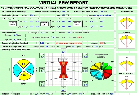
Do, automatically, one report with 10 basics points, to check the main requirements to ajust weld box to good weld.
- Slitter flow lines
- Forming radius (left and rigth + inside and outside)
- Edge off-set (misaligned edges)
- Bond line angles deviation (distorced weld line)
- Heating distributions (isothermic lines)
- HAZ (hourglass shaped relations)
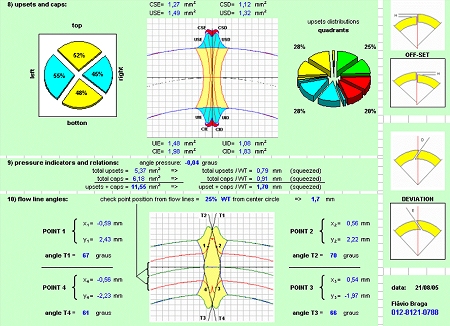
- Upsets and caps (square milimiters areas)
- Pressure indicators (squeeze out)
- Flowlines angles (several positions)
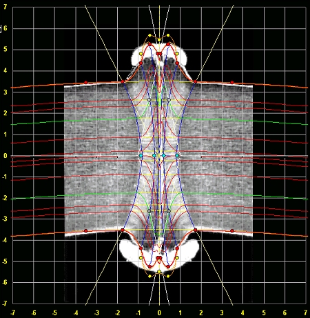
STEP 1:
- Take a digital picture from weld zone of the tube being etched Nital 3% or hot picrid acid
- Type only outside diameter and wall thickness in the excel sheet to obtain the standard graphical of weld zone (from data bank prepared before). This step provide ideal coordinates for each point required, then will be easy to ajust real points.
- The software draws a transparent graphical (ideal weld zone) over real digital picture.
- Move and ajust, size and position, from real digital picture under the ideal graphical.
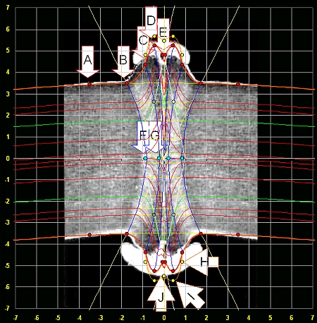
STEP 2:
- Ajust (type) coordenates from each contornous points (red points) and for each quadrant (A,B,C, D e E).
- Ajust (type) coordenates from center (blue points) for each isothermic lines (F,G)
- Ajust (type) coordenates from each contornous points (yellow points) to cap (H, I and J)
| |
Click image to enlarge
|
|
- A and B - defines external and internal radius (left and rigth)
- C and F - defines UPSETS and ISOTHERMIC 1
- D and G - defines UPSETS and ISOTHERMIC 2
- E - defines UPSETS, ISOTHERMIC 3 and DEVIATION BOND LINE
- H,I and J - defines CAP's
| |
Click image to enlarge
|
|
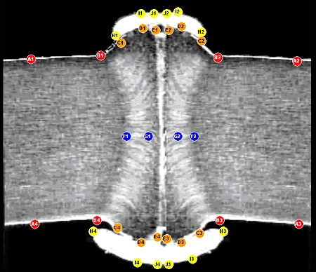
Step by step, the execution of graphical solutions:
- By claculations: radius, wall thickness, edge off-set (yellow lines), bond line deviation (interrupted yellow line), hourglass shaped (blue lines) and flowlines (red lines) are determinated.
- By integrations: individual areas, by quadrants, are calculated (heat affected zone, upsets and caps)
- By derivations: flowlines angles (green lines) are determinated (several positions)
|
| |
Click image to enlarge
|
|
REPORTS:
- By asymmetries: comparative evaluations from vertical and horizontal planes (by quadrants) in real picture are reported.
- By references standards: comparative evaluations checked against references standards could be made between real and ideal HAZ.
| |
Click image to enlarge
|
|
| |
Click image to enlarge
|
|
For further information, please contact:
Virtual Tubes and Pipes Consulting
- Attn: Flávio Braga
- Tel: 55-12-812 10788
- Download Powerpoint Presentation: http://www.pipesystem.com.br/Artigos_Tecnicos/virtual_erw-i.pps
- Email.
|