|
Effect of Heat treatment method in
minimizing the residual stress level in Cold Drawn Welded Tubes (CDW/DOM)
Sekar C K – Manager (Product &Process Development),
Sivagnanam M N- Executive (Process Development), Preethi M-Executive
(Research & Development) et al.
TUBE PRODUCTS OF INDIA, Chennai, India-600 054 |
Abstract:
Conventionally cold drawn welded tubes are stress relieved in a roller hearth
furnace. In this study, induction stress relieving is compared with the
conventional method for plain carbon steels. Technical comparison between the
two methods is conducted by mechanical properties measurement and residual
stress analysis by X-ray diffraction method.
Introduction:
Residual stress is a macroscopic stress that is set up within a metal during
non-uniform plastic deformation, as in cold drawing or thermal gradients, as in
quenching or welding. Up to 45% area reduction is employed in the manufacturing
process of CDW tubes resulting in residual stresses in the tube. These can be
tensile or compressive based on the type of cold work. Residual stress can
affect the fatigue strength and fracture toughness of the material and can cause
stress corrosion cracking and dimensional instability during further machining,
welding and forming operations. Hence minimizing the unfavorable residual stress
is an important process requirement for tubes involving critical applications.
Residual stress is usually relieved by Stress Relieve Annealing (SRA), a low
temperature annealing (350oC-600oC) in a roller hearth furnace.
Induction Heating System and Continuous Roller Hearth Furnace
Induction heating is a non-contact heating process, in which intense
electromagnetic field generated by an AC current is used to heat the job. The
shorter and higher temperature cycle in Induction heating yields the same
mechanical properties as obtained in a conventional roller furnace where the
tempering cycle time is higher. The high frequency induced generates skin
effect, which ensures that the current will flow in a thin layer in the surface
of the work-piece. This increases the effective resistance of the metal and
enhances the heating effect.
In a continuous roller hearth furnace, CDW tubes are annealed, normalized,
stress relieved or tempered with a protective atmosphere. Continuous process
lines pass through the roller furnace, at temperatures specified for the
process.
Definition of Residual Stress
When the stress applied exceeds the yield strength, the material deforms. The
internal structure adapts itself to the load applied. But there exists a stress
that can be tensile or compressive, which continue to exist in the material even
after the load is removed. Metallurgically, three kinds of residual stresses
are defined - the macro stresses (or stresses of first kind) over a few grains,
the stresses of second kind over one particular grain and the stresses of third
kind across sub-microscopic areas, say several atomic distances within a grain.
The stresses of second and third kind are also called micro stresses. (Fig.1)
Generally, compressive residual stress has a beneficial effect on the fatigue
life and stress corrosion because it delays crack initiation and propagation, as
they tend to close the cracks. Tensile stress on the contrary reduces the
mechanical performance of materials. In the elastic range, the residual stress
can just be added to the applied stress as a static load. For this reason,
compression can reduce the stress level of the layers where the applied load is
high. This leads to an apparent increase of the fatigue limit.
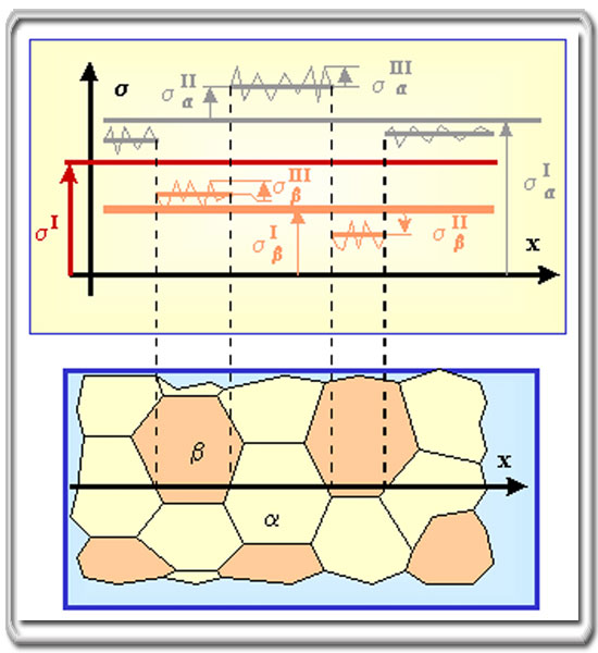 | |
Figure.1
|
|
This gains more significance in the case of cyclic loading
where cracks initiate and propagate at a stress level much lower than the yield
strength. This leads to a redistribution of the residual stress. It should also
to be noticed that residual stress relaxation, due to fatigue or annealing, and
surface layer removal (machining) produce dimensional changes of industrial
components.
Stress Relieving
Stress Relieving rearranges atoms or molecules from their metastable position to
a stable equilibrium position, associated with lower potential energy or stress
state. The cold drawn tube is heated to 3500 C- 6000 C to held at the elevated
temperature for some time and cooled to room temperature. When stress relieving
is performed at relatively low temperatures, hardness, tensile strength and
elastic properties of most cold-drawn steel are increased. The choice of a
specific time and temperature is dependent on chemical composition, cold drawing
process and the mechanical properties required in the finished tube.
Evaluation of Residual Stress
Various measurement techniques are developed to measure the Residual Stress,
which include ring core technique and bending deflection method. Advanced
technologies include X-ray diffraction, neutron diffraction, ultrasonic
technique and magnetic methods.
X - ray diffraction method uses Bragg’s law to evaluate the residual stress. The
diffraction angle calculated with the lattice spacing –measured by strain gauges
– is used for stress tensor computations.
Experiments & Results
Table 1. Chemical composition of materials
|
Grade |
Chemical composition, % weight |
|
C % |
Mn % |
Si % |
P % |
S % |
Al % |
|
SAE 1040 |
0.31-0.38 |
0.60-0.90 |
0.35max |
0.035max |
0.035max |
0.02min |
|
SAE 1541 |
0.35-0.45 |
1.35-1.65 |
0.35max |
0.035max |
0.035max |
0.02min |
|
SAE 1020 |
0.17-0.23 |
0.30-0.60 |
0.35max |
0.035max |
0.035max |
0.02 min |
| |
|
|
Table.2
Summary of Stress Relieving details
|
Size (mm x mm) |
Grade |
Temperature |
Sample Identification |
|
Induction |
Roller hearth |
|
30.00 OD X 2.00 WT |
SAE
1040 |
T1 |
SRAISRA-1 |
SRARH-1 |
|
26.08 OD X19.00 ID |
SAE
1541 |
T2 |
SRAISRA-2 |
SRARH-2 |
|
44.45 OD X 36.53 ID |
SAE
1020 |
T3 |
SRAISRA-3 |
SRARH-3 |
| |
|
|
Table.3
Physical properties of material at different conditions
|
Grade |
SAE 1040 |
|
TYPE |
AS DRAWN-1 |
SRA RH-1 |
SRA ISRA-1 |
|
Mechanical Properties |
UTS (MPa) |
808 |
860 |
878 |
|
YS (MPa) |
670 |
722 |
738 |
|
EL% |
9 |
10 |
13 |
| |
|
|
|
Grade |
SAE 1541 |
|
TYPE |
AS DRAWN-2 |
SRA RH-2 |
SRA ISRA-2 |
|
Mechanical Properties |
UTS (MPa) |
1005 |
971 |
994 |
|
YS (MPa) |
834 |
816 |
835 |
|
EL% |
14 |
19 |
19 |
| |
|
|
|
Grade |
SAE 1020 |
|
TYPE |
ASDRAWN-2 |
SRARH-2 |
SRA ISRA-2 |
|
Mechanical Properties |
UTS (MPa) |
605 |
595 |
594 |
|
YS (MPa) |
502 |
494 |
499 |
|
EL% |
20 |
31 |
31 |
| |
|
|
Residual stress testing procedure & results
A spot is identified for testing and is electrolytically polished. The variables
for polishing are selected based on the material and conducted as per the
guidelines from ASME handbook.
The scattered X-rays from a chromium target from the irradiated atoms/crystals
are reinforced in a specific direction of an extremely narrow range and
propagated. The schematic of the XRD set up used is indicated in Fig. 2. The
condition of diffraction is met using Bragg’s law, nl = 2d sinq, where d is
inter atomic spacing, q is the Bragg’s angle and l is the wavelength
characteristics of the X ray radiation. The diffraction patters so obtained is
measured for various Y angles i.e., 0,5,10,15,20,25 and 40. (Y = Yo+ q), in
terms of a shift in 2q, which accounts for a change in the inter planar spacing.
If tension is applied in parallel to the sample surface, the applied tension
will act on the different groups of crystals in different angles, as force is a
vector. Accordingly the inter planar spacing will vary with respect to the angle
between the sample plane and the lattice plane. The stress value is determined
from the slope of the plot of 2q Vs sin2Y.
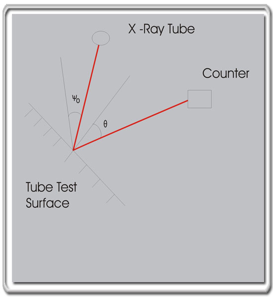 | |
Figure 2.
|
|
Stress s = K x D (2q/ sin2Y)
K = -1/2 x [E / (1+m) ] cot q (p/180)
The variables in the X-ray measurements like the type of target material used,
(Chromium, cobalt or copper.) measurements method (Fixed Y method or Fixed Y0
method), tube current stepwidth, low / high 2q angle, oscillation number, fixed
time etc. are standardized on case-to-case depending up on the material /
component, texture, grain size (coarse or fine grained) etc.
Residual stress measuring was carried out on three types of steels listed in
Table 4. Negative values indicate compressive stress and positive values
indicate tensile stress.
Table.4 Summary of X-Diffraction Test Results
|
Sample Identification |
Size |
Grade |
Residual stress |
|
(MPA) |
|
SRA AD-1 |
30.00 mm OD X 2.00 mm WT |
SAE 1040 |
-91 |
|
SRA AD-2 |
26.08 mm OD X19.00 mm ID |
SAE 1541 |
-155 |
|
SRA AD-3 |
44.45 mm OD X 36.53 mm ID |
SAE 1020 |
-140 |
| |
|
|
|
Sample Identification |
Size |
Grade |
Residual stress |
|
(MPA) |
|
SRA RH-1 |
30.00 mm OD X 2.00 mm WT |
SAE 1040 |
+37 |
|
SRA RH-2 |
26.08 mm OD X19.00 mm ID |
SAE 1541 |
-61 |
|
SRA RH-3 |
44.45 mm OD X 36.53 mm ID |
SAE 1020 |
-25 |
| |
|
|
|
Sample Identification |
Size |
Grade |
Residual Stress |
|
(MPA) |
|
SRA ISRA-1 |
30.00 mm OD X 2.00 mm WT |
SAE 1040 |
-17 |
|
SRA ISRA-2 |
26.08 mm OD X19.00 mm ID |
SAE 1541 |
+23 |
|
SRA ISRA-3 |
44.45 mm OD X 36.53 mm ID |
SAE 1020 |
-12 |
| |
|
|
AD indicates As Drawn
Results
Stress relief annealing using a continuous roller hearth furnace and induction
heating system are compared. The following are the observations established from
this study.
The tensile properties of medium carbon steels was shown to be higher for
samples SR annealed in an induction heating system, without compromising the
elongation properties of the material. For low carbon steels, both the processes
yield almost the same result.
Surface residual stresses in the material decrease using both methods. However,
the values close to the no-stress range are observed after SR annealing in the
induction heating system.
Induction heating system can be used for small batch production and development
and research activities. This is the result of conformance to the desired
properties – as conventionally obtained using a roller hearth furnace – along
with the inherent advantages of higher speed, reduced dwell periods, selective
heating capability to produce quality parts (at lower cost), lower space
requirement and better operating environment.
The residual stress analysis in this study is limited to the surface of the
material. Therefore further studies are required to compare the core residual
stress of the material after the two processes, the extent of residual stress
relief required to achieve the desired properties and to conclude the better
between the two SRA processes.
Contact Person:
Sandeep Mathew Olickal/Sekar C K,
Process Development,
Tube Products Of India – Exports Division,
M.T.H Road, Avadi, Chennai,
INDIA – 600 054
Ph: 91-44-2638 3338
www.tubeproductsofindia.com
|