Factors Influencing Heavy Wall Tube Welding
by John Inge Asperheim, Bjørnar Grande, EFD Induction as
Introduction
Induction welding of tube and pipe with increased wall thickness
presents manufacturers with new challenges regarding production
rates and quality.
In a medium- and thick-wall tube the heat-affected zone (HAZ) is
shaped like an hourglass, ie the corners are heated more than the
centre of the tube walls. A cold centre can limit the maximum weld
speed, even if the mill has additional capacity and the welder has
additional power.
Compensating with more power to sufficiently heat the cold centre
can overheat the strip edges considerably. Weld quality can
deteriorate and the overheated edges may cause molten material to
drop onto the impeder, reducing impeder lifetime and performance.
To understand this weld problem better, we have studied
parameters influencing the temperature distribution across the weld.
These parameters are Vee angle, distance from weld point to induction coil, spring back, weld speed and frequency.
Computer Simulations
Two-dimensional, coupled electromagnetic and thermal FEM
analyses enable us to investigate the development of
temperature in the cross-section of the weld Vee from induction
coil to weld point (see figure 1), as well as the final distribution
at the weld point. For details, see ref. [1] and [2]. The metal strip
material in all our calculations is low-carbon steel with a wall
thickness of 12.7mm (0.5").
| |
Figure 1. Development of temperature distribution in the Weld Vee
|
|
The minimum temperature required in the cross-sectional centre of
the tube, to avoid cold weld condition, is a function of the applied
weld roll pressure. In this case, we use a temperature of 1250°C in
the tube wall centre at the weld point.
Some results are presented as colour shade plots of the
temperature distribution at the weld point. The temperature
scale for these plots is shown in figure 4.
To compare the setups, we have calculated the cross-sections of
molten (above 1725°C) and partly molten (above 1550°C) material
from the temperature colour shade plots. The size is given in
percentage of the cross-section of a reference setup (200kHz, 3°
Vee angle and 14.6m/min mill speed).
| |
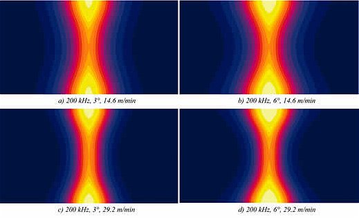
Figure 2. Temperature distribution at the weld point
|
|
| |
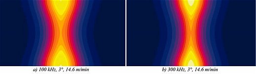
Figure 3. Temperature distribution at the weld point
|
|
| |
Figure 4. Temperature (°C) scale in figure 2 & 3
|
|
Vee angle and Springback
Figure 2 shows some results for a 200kHz setup. An increase in Vee
angle from 3° to 6° increases the amount of molten material by
about three times at low speed and two times at high speed. The
amount of partly molten material increases approximately 50 per
cent for both mill speeds.
Figure 5 shows that there is almost a linear relationship between
melting and Vee angle. The effect of springback is investigated for
200kHz. This Vee shape is based on measurements on a mill
running similar tube dimensions. At the beginning of the calculation,
the distance between strip edges is equal to that of a linear Ve e
with 3° angle. Springback has the same effect on the weld problem
as an increased Vee angle. In this case it equals a 4° angle for a
linear Vee .
| |
Figure 5. Melting vs Vee angle; 200 kHz, 14.6 m/min
|
|
Vee angle and Mill Speed
Temperature distribution along the tube wall centerline (x-axis) is
mainly affected by speed and, hence, heating time. Increased speed
results in more heating of the tube wall corners. The result is a more
pronounced hourglass shaped heated zone.
This effect is most evident in figure 2d, with the combination of highspeed
and wide angle. Results show that the 3°, 29.2m/min setup
gives less temperature differential in the weld zone than 6° and
14.6m/min. In figure 6 we can see that even a 1.5° reduction in Vee
angle gives a better result.
Assuming constant Ve e - Welder power ratio, a reduced Vee angle from
6° to 3° reduces Vee-power consumption with 12 per cent. This allows
an 18-20 per cent increase in mill speed for the same power.
Vee Angle and Frequency
Figure 6 displays the temperature distributions for 100 and 300kHz
at 14.6m/min. There is a distinct difference in the amount of molten
material for the two frequencies.
| |
Figure 6. Molten material vs. frequency
|
|
Focusing on the increase in Vee angle, (see figure 6) we see that
twice the Vee angle has a greater impact on melting than three
times the frequency.
The results indicate a narrower heated zone at higher frequencies.
Energy input to the weld zone, however, is not correspondingly low
[2]. Overheated strip edges increase the energy consumption at
higher frequency.
Induction Coil Position
The influence of distance between weld point and induction coil can
be investigated by assuming an ideal linear Vee. The results for 6°
and 14.6m/min (at nominal distance, as for all simulations) equal the
results for 3°, 29.2m/min at twice the nominal distance.
Figure 7 shows melting vs. frequency with distance as parameter.
It is evident that the induction coil should not be positioned
unnecessarily far away from weld point, independent of
f r e q u e n c y.
A long Vee increases both heat flow away from the weld Ve e ,
and stress on the impeder. This gives a higher needed energy
input and, in some cases, a matching limitation due to low
i m p e d a n c e .
| |
Figure 7. Molten material vs. frequency
|
|
Factors influencing Overall Performance
The requested impeder cross-section is calculated on the basis of
Vee voltage and frequency. Both the energy input and necessary
impeder cross-section can be reduced by one or more of the
following setup changes:
- Reduced Vee angle
- Less springback
- Shorter distance from induction coil to weld point
These three changes work together, or alone, in reducing the area,
AV, of the weld Vee; see figure 8. This area should therefore be
made smaller in order to increase the throughput due to:
- Reduced problem with cold centre and overheated edges.
- Improved overall welding efficiency.
These benefits, given by reduction in weld Vee area, are
independent of frequency.
| |
Figure 8. Weld vee
|
|
For the same mill setup and speed, a lower frequency demands a
bigger impeder cross-section. This can be compensated with a
reduced weld Vee area. A 1.5° reduction in Vee angle equals a
100kHz step down in frequency.
Low frequency requires a larger impeder cross-section, but for big
diameter tube production, this is not the limiting factor. It can therefore
be possible to take advantage of the favourable heat-affected zone for
100kHz where there is less temperature differential in the weld zone.
On thick-wall, small diameter tubes, however, impeder space is
limited. In addition to optimising impeder position, size and cooling,
it might be necessary to reduce the weld Vee area for lower
frequencies in order to achieve high-performance production.
| Conversion Table |
| 1250°C = 2280°F |
| 1550°C = 2822°F |
| 1725°C = 3137°F |
|
| 14.6m/min = 47.9ft/min |
| 29.2m/min = 95.8ft/min |
References
[1] J.I. Asperheim, B. Grande, L. Markegård, J.E. Buser, P. Lombard, "Temperature distribution in the cross-section of the weld Vee", Tube Int., November 1998
[2] John Inge Asperheim, Bjørnar Grande, "Temperature Evaluation of Weld Vee Geometry and Performance", Tube Int., October 2000
For further information or a demo-version please contact:
EFD Induction AB
- Attn: B. Grande and J. I. Asperheim
- Addr: PO Box 760, N-3701 SKIEN, NORWAY
- Tel: +47 35 50 60 00
- Fax: +47 35 50 60 10
- WWW: http://www.efd-induction.com
- Email.
| 
