Maximizing uptime in high-frequency tube and pipe welding
By Bjørnar Grande, John Kåre Langelid, Olav Wærstad, EFD Induction
Abstract
This article explains some basic principles of solid-state welder design that are crucial for
maintaining operation under various conditions. The paper also presents several key differences
between MOSFET and IGBT transistors, and describes how a converter with a voltagefed
inverter and series resonant output circuit withstands short circuits.
Introduction
Tube and pipe manufacturing professionals know the best days are when nothing unexpected
happens when the line works as it should, delivering maximum uptime and throughput.
And all of us also realise that the solid-state welder plays an absolutely critical
role in achieving and maintaining maximum uptime.
Maximum welder uptime requires more than attention to overall circuitry design. Close
attention must also be paid to the reliability of each of the components, both in normal
and demanding operating conditions. High reliability in steady-state operation is ensured
by being in control of the power losses and cooling of the power transfer components. The
design must also maintain required margins in relation to maximum component ratings for
voltage, current and temperature. Finally, the welder must be able to operate as desired with
extremes of water and ambient temperature.
For many welders the loss of steady-state operating conditions is usually caused by a short
circuit in the load. Arcing can occur between strip edges in the weld vee, between strip and
induction coil, or between coil turns or terminals due to slivers and burrs in the weld zone.
A welders ability to cope with short circuits in the load is, first of all, related to the inverter
and the solid-state switches shortcircuit handling capability. The first part of this paper
covers aspects to consider regarding the choice of transistors in the inverter of a welder for
high-frequency tube and pipe welding.
Short circuit operation
In the tube and pipe industry the output circuit of a welder is available as either a series or
parallel resonant circuit. A widely held misconception is that a voltage-fed inverter with a
series resonant circuit has inherent problems with short circuits in the load. This misconception
stems from the mistaken belief that an arc across the coil causes a flow of high current. On the
contrary, what happens is that the resonance point is shifted upwards in
frequency. In a series resonant circuit with a high Q-factor, the impedance increases sharply
when operating out of resonance and the current drops. [1] The rest of this section explains
the events that occur during a short circuit of the series resonant circuit.
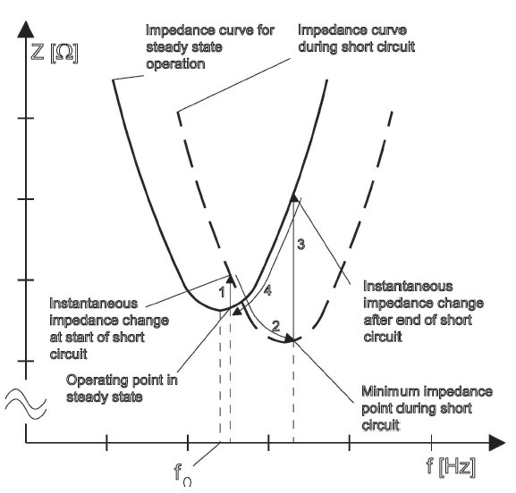
Figure 1 shows the impedance changes seen from the voltagefed inverter during a short circuit
in the coil. At the instant the arc occurs, the resonance frequency of the output circuit
increases and the impedance curve moves up in frequency. The switching frequency of the
inverter does not change instantaneously and the inverter will face higher impedance. Arrow
one in figure 1 shows this instantaneous increase in the impedance, which results in a current
drop from the inverter. Switching frequency increases rapidly towards the new, higher
resonance frequency. With the fast current regulation in the inverter, there is enough time
for a controlled change of current towards the new operating point, slightly above the new
resonance frequency (see arrow two). When the short circuit disappears, there is an instantaneous
decrease in resonance frequency and a corresponding increase in impedance, shown
by arrow three, followed by the final adjustment back to the previous steady state operating
point. No high and dangerous current occurs either in the inverter or elsewhere in the welder
due to the short circuit.
| |
Figure 1
|
|
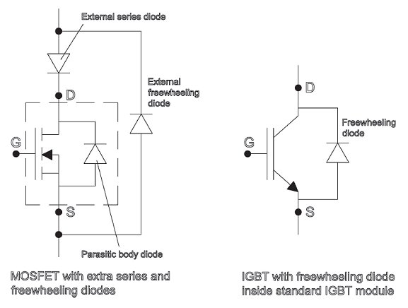
When a coil short circuit occurs, the load resonant frequency increases. This causes current
zero crossing to happen before inverter voltage switching. This type of switching is termed
capacitive switching. Using a MOSFET without a series diode considerably raises the risk of
activating the MOSFETs parasitic bipolar transistor (see figure 2). This will immediately destroy
the MOSFET transistor. There are ways to prevent this, but they have drawbacks such
as startup problems and difficulties recovering from a short circuit during welding.
| |
Figure 2
|
|
In IGBT transistor modules there are added ultra-fast and softrecovery freewheeling diodes.
These make a short across the coil completely harmless for the IGBT inverter provided
there is a function to limit how long the arc is allowed to burn. Short circuits in the load
in tube and pipe welding are in this context very short. In fact, due to EFD Inductions fast
regulation of frequency and current, IGBT transistors even survive long-duration short circuits.
A video demonstration of this can be seen on the EFD Induction website[2].
Current sharing between transistors and inverter modules
Almost all manufacturers of welding machines today use the principle of a modularised
inverter. In order to get the required output power, several inverters are stacked to operate
in parallel. Several inverters connected in parallel on both the DC and output sides require
stringent control of the turn-on and turn-off of the transistors. The timing in the driver
technology is critical, especially in the case of inverters using MOSFET transistors. This is
because parameter spreading in MOSFETs is relatively large, which causes variations in the
transistors turn-off instants among paralleled devices. The slowest transistor to turn off is
likely to be destroyed, due to unevenly distributed power loss among the devices. This is the
main reason why replacement MOSFETs must be carefully selected prior to installation. It is
also the reason why replacement inverter modules for certain MOSFET welders must first be
tuned to a specific location in the inverter stack.
IGBT transistors, however, can be used off the shelf. There is no time-consuming measuring
and pre-selection. This is due to the extremely well proven production process of the
non-punch through (NPT) IGBT chips. The production process gives a very tight spread in
parameters (such as time delay on/off and gate threshold voltage) compared to epitaxial
grown MOSFET transistors.
In the EFD Induction welder there are no restrictions on module positioning in the inverter.
Position does not affect current distribution among modules, as the overall circuit design
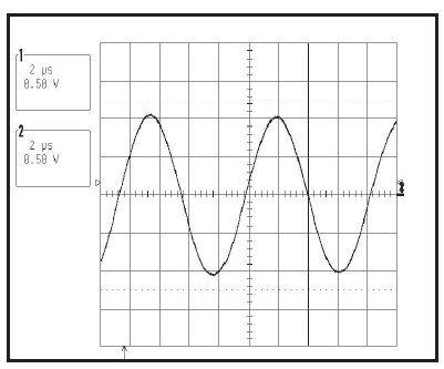
guarantees 100% equal current sharing between all inverter modules (as is shown in Figures
3 and 4). There is no need to select driver boards based on time-delay differences. Figure 3
shows the current from two inverter modules, one positioned at the top of the inverter, the
other at the bottom. It is difficult to see that these are the current signals from two inverter
modules, since they are in fact 100% identical. Figure 4 is therefore the same as Figure 3,
but with channel two shifted down one division to show that there are two measured currents.
| |
Figure 3
|
|
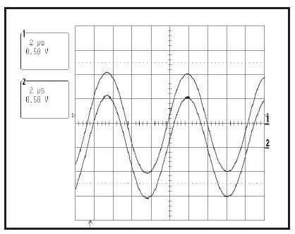
| |
Figure 4
|
|
With 100% equal current in all inverter modules together with the homogeneity of the
transistor modules power loss among inverter modules and operational temperatures of
the IGBT transistors are extremely consistent and controlled. Furthermore, at 35°C (95°F)
water inlet temperature to the welder, EFD Inductions design criterion is for a maximum
75°C (167°F) chip temperature inside the IGBT transistor module. The rated maximum chip
temperature of the transistor module is 150°C (302°F). The benefit of this system is that
both module and system reliability are maintained at the highest level.
IGBT at high frequencies
Until EFD Induction introduced its patented switching technique for IGBT transistors, the
generally accepted highest frequency range for IGBTs was 125-150kHz. Above this level
switching losses became too high without considerable de-rating of output power, making
the component uneconomical. Compared with standard, traditional switching technologies,
EFD Inductions patented section split system makes the maximum effective switching frequency
for one IGBT module of a 400kHz system to be one quarter, that is, 100kHz switching
for each IGBT module. This makes the driving of the IGBTs much easier compared to a
standard de-rating technique (less driver losses at turn-on and turn-off). A weld frequency of
500kHz with IGBT-based inverter modules is now readily available. The major benefit is the
high increase in efficiency compared with a traditional de-rating technique. Based on the
same loss level, EFD Inductions section split system gets 2.53 times as much power out
of the same IGBT chip area compared to less sophisticated methods. The overall benefit for
tube and pipe manufacturers is efficient power transfer at high frequencies with the IGBT
transistors extremely high reliability.
Output circuit
A specific weld process with a specific frequency, coil current, output power and coil
results in a coil voltage that is independent of the brand of welder used. The laws of physics
dictate that low internal inductance results in low total voltage. Any added adjustable series
inductance (such as for power matching or frequency adjustment) adds extra voltage. As
a result, the compensating capacitor voltage installed inside the unit must be higher. The
EFD Induction welder is designed with low, and no extra, internal inductance in order to
secure low voltage operation.
High-power output compensation capacitors are a vital part of a welder. Commercially available
capacitor types tend to have either too high internal inductance or a mechanical design
which do not take into account the thermal expansion of the capacitor elements during
operation. EFD Induction-made capacitors are low-inductance, high-current modules, and
are specifically designed for high-frequency welding applications. To ensure long lifetime,
two main design criteria are a maximum hot spot temperature of 70°C (158°F) at maximum
reactive power, and an allowance for thermal expansion of the capacitor elements. The design
is well proven and has been improved and refined over the past 20 years. The numerous
internal capacitor elements are double-sided watercooled in order to secure high current
and high reactive power operation. Flow switches monitor the water flow, and each capacitor
module has a dedicated thermostat for additional protection.
Some welders with a parallel resonant output circuit use variable series inductance as a
way of obtaining some matching capabilities. The major disadvantage of this solution is the
number of moving electromechanical parts in the output circuit, which are prone to wear
and jamming. Should relays and electrical motors be used for controlling, these components
are also likely to face fatigue problems. The EFD Induction Weldac has automatic electronic
load matching in the inverter which does not require the continuous operation of moving
mechanical components[3].
No extra mains transformer maintenance
In a welder with no intermediate transformer, the output circuit is not isolated from the mains
supply. A mains transformer is then required, either installed outside or inside of the DC
power supply cabinet. Where transistors with low-breakdown voltage are used in the inverter,
a transformer is also needed to adapt to the factorys higher mains supply voltage. It is especially
critical that welders with power control in the SCR have very precise control and firing
of the thyristors in the rectifier. This is to avoid non-symmetric load of the three windings in
the mains transformer. Incorrect adjustments and timing differences result in non-symmetric
stress, which reduces maintenance intervals and/or lifetimes of mains transformers.
The EFD Induction welder includes an intermediate, low-loss transformer for both load
matching and galvanic separation purposes. A mains transformer to insulate the output
circuit from the mains is not required. Because of power control in the inverter, the EFD
Induction welder uses a passive diode rectifier. This does not cause any non-symmetric load
or stress on any mains transformer in the tube manufacturers factory power supply grid,
further enhancing uptime. The output compensating capacitors in the output circuit are on
the secondary side of the intermediate transformer. Due to this, no reactive power transfer
takes place in the transformer and a low voltage operation is secured. The windings and core
are moulded in a resin without any oil content.
No extra mains transformer maintenance
The EFD Induction welder is designed to operate at ambient temperatures of 5° to 50°C (41°
to 122°F). All power components inside the cabinet(s) are water cooled. The water-cooling
circuits are designed for a water inlet temperature of 35°C (95°F), and flow is monitored by
flow switches. Several components are additionally protected by thermostats. Furthermore,
a water/air cooler is installed inside the cabinet(s) to keep inside ambient temperature
within the range for all components, including the electronics. The cooling water temperature
is controlled by the water/water-cooling system to keep the water temperature inside the
cabinet above the dew point. Where necessary, an air conditioning unit is included for extra
safe operation. No parts of the welder need a dedicated chilled room when operating in high
ambient temperatures.
Summary
A successful welder design for high-frequency tube and pipe welding must maximise uptime
and throughput. To achieve this objective in the relatively harsh environment of a tube mill,
EFD Induction has designed the Weldac. The following were key design objectives:
- The welder must be able to withstand short circuits
- The welder must work with high ambient and cooling water temperatures (caused for
example by climate conditions)
- The welder must operate with the lowest possible voltage in the output circuit
- The welder should not feature continuously operating mechanical parts (in order to
avoid problems caused by fatigue, wear and jamming)
- The welder should feature readily available components (such as off-the-shelf IGBTs).
The Weldac is based on a voltage-fed inverter and a series resonant output circuit, and easily
handles short circuits. No large currents or overvoltages occur during short circuits. This
type of welder operates safely and reliably over a very wide frequency range.
EFD Induction has 30 years experience with solid-state switches in the inverters of induction
heating equipment. During the last 20 years, EFD Induction has gained extensive experience
with both MOSFET and IGBT transistors in high-frequency tube and pipe welding.
Where consistently high uptime and output are priorities, the IGBT transistor is the inverter
switch of choice:
- The IGBT has an intrinsic short-circuit handling capability: it is an extremely rugged
component
- Because of tight parameter spreading, the IGBT is the best choice for paralleling of
transistors. Combined with the patented section split system (which improves current
sharing among paralleled transistors and reduces the required number of paralleled
transistors) this gives a very reliable system
- The IGBT is a widely available and standard industrial transistor. Unlike MOSFET welders,
there is no need to carefully select and tune transistors and inverter modules.
The overall benefit for a tube and pipe manufacturer is efficient power transfer at high frequencies
(70-500kHz) with IGBT transistors extremely high reliability. One consequence of
this rugged design is that EFD Induction is the only tube and pipe welder manufacturer to
offer a five-year warranty for the systems inverter modules and driver cards.
References
- N Mohan, WP Robbins, TM Undeland, (1989) Power Electronics: Converters, Applications
and Design, John Wiley.
- www.efd-induction.com/en/bestwelder
- F Kleveland, JK Langelid, L Markegård, (2003) New HF Converter for Induction Heating,
Proceedings of the International Conference on Electromagnetic Processing of
Materials, Paris.
For further information or a demo-version please contact:
EFD Induction
- Attn: Bjørnar Grande, John Kåre Langelid or Olav Wærstad
- Tel: +47-35 50 60 00
- WWW: http://www.efd-induction.com
- Email.
|