Calibration Standards for High Performance Tubes & Pipes
By Mark B. Palynchuk, Western Instruments Inc.
Calibration (Reference) Standards are required for a standardized and reproducible reference on which to base acceptance and rejection of "naturally" occurring defects. Calibration Standards have "artificial defects" machined into them that are required by either industry specifications, by end users or for internal control so that initial and periodic calibration of non-destructive testing equipment can be verified. Calibration ensures that the equipment accepts or rejects injurious defects with respect to the artificial defect on a repeatable basis.
Calibration Standards for ultrasonic testing are based on the energy reflected from an artificial defect, however, some specifications also require verification at mill or conveyer lines speeds. Speed criteria involves energy reflected within a period of time that must also be considered to ensure that minimum sized defects are detected.
Historical Background
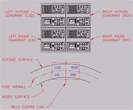
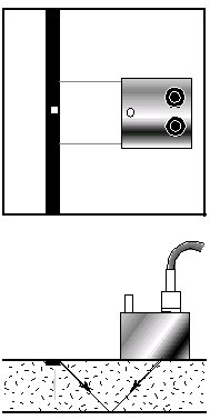
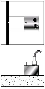
In the early years of ultrasonic testing for weld defects, notches were used as artificial defects, because of their previous use as in manual testing, in part because large transducer elements were being used, obviously at low speeds. Notches provided a means of aligning the transducer with respect to the longitudinal axis of the tube and in turn the weld. First multi-channel weld testers were developed to deal with geometric characteristics of defects. [See Figure 1]
| |
Figure 1: Sensitivity zones to address OD/ID and LEFT/RIGHT defect geometry.
|
|
The advent of radio frequency welding, and increased material strengths required the ability to detect short penetrator type of defects. Short, small defect detection necessitated the development of high speed alarm monitors and improved transducer technology as it became obvious that the large transducer elements of the day were not suitable.
|
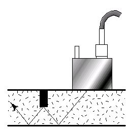
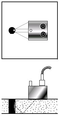
Figure 2a) Reflection from flat bottom
half hole is not reflected back.
|
|
|
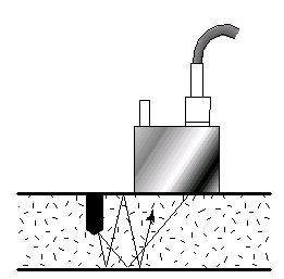
Figure 2b) Reflection from drilled half hole
reflects back energy, increasing effective
reflected energy
|
|
| |
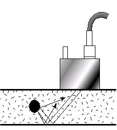
Figure 2c) Reflection from end hole
|
|
Multi-channel testing was first introduced in practical form in approximately 1960 by a pipe manufacturer. The probe characteristics are important but are beyond the scope of this paper.
To ensure defects were detected at mill line or conveyor line speeds it was recognized that much higher pulse repetition frequencies were required. Initial pulse repetition frequencies were in the 60 Hz to 90 Hz and today rates are typically well over 1000 Hz. The combination of low pulse repetition frequency, large transducers along with inadequate monitors did not permit the detection of short, small defects and this resulted in the abandonment of hundreds and even thousands of miles of pipelines (essentially unpublicized).
It is apparent a drilled hole is far more representative of penetrator type defect. The multi-channel testing systems demonstrated the need for balancing sensitivity to ID and OD type. Coupled with increasing need to detect a penetrator type of defects, the concept of half holes from the ID and the OD as well as through holes was utilized due to their sound reflection areas.
| |
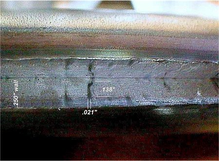
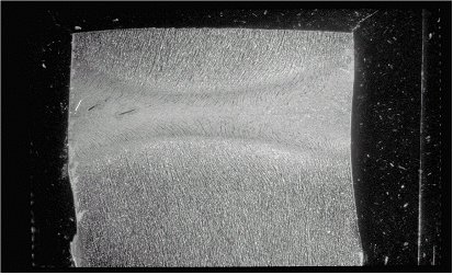
Figure 3A: Crush test of a typical defect picked up by Ultrasonic testing methods
|
|
| |
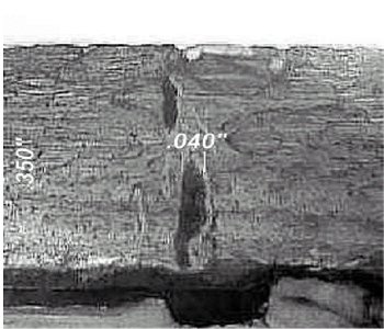
Figure 3B: Typical defect picked up by Ultrasonic Test Methods.
|
|
|
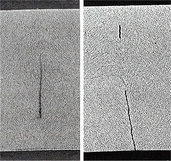
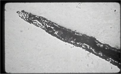
Figure 3c) [Left]: Photomicrograph of a defect picked up by Ultrasonic testing.
Figure 3d) [Right]: Photomicrograph of a defect picked using ultrasonic testing.
|
|
Furthermore, as wall thickness' got even heavier and the wall thickness to diameter ratios decreased, an additional concern about the sensitivity to detect mid-wall defects was raised. This mid-wall concern lead to the development of holes drilled into the end of calibrations standards ensuring both probes could identify half holes on the opposite side. [See Figure 2a) 2b) 2c) and Figure 3]
Machined Notches
As previously referred to, notches evolved out of their use in manual testing. Notches are typically 1" to 2" long and are specified for calibration standards. It has been found that to obtain reproducibility testing from one direction and then the other direction, and going from one standard to another, it is expensive to set these up (Capital Costs) whether electro-discharge machining or custom machines are used. Furthermore, it is expensive to reproduce, particularly the time to do all the checking of the setups that are required and requires significant skill development to produce these. [See Figure 4a), b), and c)]
Furthermore, notches are a representation of surface defects and open seams. They do provide the facility for checking the alignment of the probe to the center line. They are very useful as a quick reference as they are long and highly reflective. We will discuss an alternate method of checking the probe alignment to the axis of the tube.
Drilled Holes
Holes as can be seen in the Figures 2a) to 2c) are far more representative of short, small defects. The actual reflective area is not the diameter of the hole, but is a fraction of it as is illustrated in the Figures 4a) and 4b). Holes are relatively inexpensive to reproduce and the procedures for doing these are well established.
Half holes ensure mid-wall sensitivity when using multi-channel units on heavier wall thickness'. As mentioned previously, holes represent short defects and small reflective area defects. It is important for half holes to be flat bottom and illustration 2b) shows the reason for this.
However, no matter how small a hole you calibrate your system on and its capability to detect such small defects, ultrasound is not capable of picking up metallurgical differences such as those found in cold, or paste welds, because unless there is a physical reflection which will reflect ultrasound there is no meaningful test. Cold and paste welds can be detected by ultrasound but only if there is a reflector type of defect associated with such metallurgical conditions. [See Reference]
An alternate method for checking the alignment of the probe with respect to the axis of the pipe is the use of a hole drilled into the end of a calibration standard, (Figure 2c) as has been previously discussed, for checking on the sensitivity to mid-wall defects because this also provides a very large reflector similar to a notch. Again, these are relatively easy and inexpensive to produce as compared to good quality notches.
|
Figure 4a) Reflection from a 10% notch.
The defect area is below the notch.
|
|
|
Figure 4b) Reflection for a 5% notch.
The defect area is below the notch.
|
|
|
Figure 4c) Reflection from drilled through hole.
The defect area is centered where the largest power
per unit area is. That is along the central path from
the transducer.
|
|
Comparison and Analysis of Reflective Areas
The following analysis is a simplified model that illustrates the differences between the two types of artificial defects described herein. Further, it applies the results to a real world, "natural" defect that yields order of magnitude results. Some assumptions are; the probe is a contact probe with a square, 0.5" x 0.5" , transducer produces sound waves that travel along parallel rays, the tube is represented by a flat plate 0.25" thick to simplify the geometry (small diameter tubing would require a more rigourous treatment), the same probe is used on the notch and the through hole, and that the characteristics will be similar to both artificial defects.
Calculations of the effective reflective area to the pipe for a 1/8" through hole give 0.025" x 0.250". If we calibrate this drilled hole to 100% of signal on our display, we can estimate the % signal that a specific size defect will make. For example, if we choose a typical defect like figure 3a) with dimensions 0.021" x 0.138". The ratio of power input to power returned is equal to the ratio of the areas squared. Taking the base ten logarithm and multiplying by 10 will give us the dB drop of the signal. From this we can calculate the % signal produced by the typical defect. For a typical gain setting of 50 dB the defect will be represented by an 87% signal. For a 10% notch the effective area will be (0.025" x 0.50"). This results in a gain setting for the 10% notch (relative to the typical gain for the 1/8" drilled through hole) of 44 dB to obtain 100%. The notch calibration however only returns about half the effective area of the typical defect because it is located midwall not at the OD where maximum signal in a notch is located and calibrated to. Therefore, a typical defect will then be represented by a 57% signal. The 5% notch will have the same relative gain setting of 50 dB with a typical defect being represented by a 75% signal. Typical gate levels are 80% for reject and 60% for warning. The defect calibrated on a 1/8" through hole is easily picked up by the reject gate. The 10% notch however does not even trip the warning gate, while the 5% notch trips the warning but is significantly below the reject gate.
Selection of Materials for Calibration Standards
Sections of pipe that are representative of the materials being produced must be used. This includes diameter, wall thickness, shape and metallurgy. The area of the tube where the artificial defects are to be generated should be checked ultrasonically to ensure that there are no internal reflectors that would complicate the use of the calibration standards. It is generally preferable to select areas in the 3 or 9 o'clock positions. The testing should include both compression and shear wave to ensure the pipe section is clear of such internal reflectors. Going to these precautions avoids having to reject calibration standards after all the expense has been incurred in generating them.
Summary
As shown in the previous part of this paper, the actual reflecting area of a hole as an artificial defect is not the diameter of the hole, but is very much reduced as can be seen from the graphical representation of an ultrasound beam interacting with a hole and a notch. Reflection from the hole is illustrated as shown in Figure 4c).
It is important for each manufacturer to determine the type of defects that are injurious for the particular products that are manufactured by a mill. If the short defects that have been emphasized in this paper are not of a concern, then the use of notches is certainly a viable approach. However, with the increasing demand for uses of welded tubular products such as boiler tubes, oil country tubulars (including line pipe), tubes used for hydro-forming, drawn over mandrill products, etc., notches are not applicable.
| |
Figure 5a): Micro of small hook cracks near weld interface similar to a weld line defect.
|
|
| |
Figure 5b): SEM of tip of crack in 5a) Magnification 67X
|
|
| |
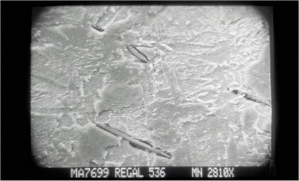
Figure 5c): SEM of 5a) Magnification 2,810X
|
|
| |
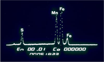
Figure 5d): SEM of Figure 5a) X-Ray spectrum
|
|
REFERENCE:
Cold Weld Detection: Non-Destructive Testing Means & Experimental Review, A. Palynchuk, Tube 2000 June 1998
For further information please contact:
Mark B. Palynchuk, Western Instruments
- Addr: Box 72, Site 2 RR1, St Albert, T8N 1MB, Canada
- Fax: +1 403 459 7837
- WWW: http://www.westerninstruments.com
- Email.
|