Modern Methods of High Frequency Welding
Used to Produce Consistent Quality
By Mr. Theodore Morin and Dr. Paul Scott,
Thermatool Corp., CT, USA
Historical Perspective
The high frequency welding process as applied to pipe and tube manufacturing is indeed an enigma! Seldom in the history of metal product manufacturing has a process been so successful for so many decades and at the same time so little understood. Certainly this attests to the forgiveness and value of this process. Thousands of tons of quality pipe and tube are produced daily by manufacturers with very little or no knowledge of the process whatsoever.
Now that less forgiving high frequency welders are coming into the market operators will have to pay more stringent attention to correct set-up practice. Solid state welders are more efficient, safer and produce a higher quality of RF power than vacuum tube welders but they are far less forgiving - this is particularly true for the lower frequency welders on high speed tube lines.
Current Experience
There are more than 100 solid state welders installed and most are trouble free and produce high quality forge welds. They operate in the frequency range of 150 kHz through 800 kHz and through a power range of 50 kW through 1000 kW. Multi-frequency and variable frequency systems are also available. The nature of the electronic design allows far more options and features than would be possible with vacuum tube technology.
Welding results are excellent. Typically, ripple on the RF is greatly reduced resulting in improved I.D. bead size and shape. The lower output voltages lead to significantly less coil arcing to the pipe. When properly applied, they use far less power and cooling water than their vacuum tube counterparts.
Recent R&D
During the past two years there have been important breakthroughs in both theoretical and experimental work in high frequency welding. In mathematically deriving a simple algebraic expression that told us what the real RF power in the welding vee actually depends on, we were able to define a "critical frequency". With this understanding we learned how to produce higher quality welds with narrower heat-affected zones (HAZ). This has all been verified on an actual tube mill under carefully controlled circumstances.
The very latest theoretical work helps us to better understand the forces needed to squeeze the melted material from the seam. We are able to analytically describe the temperature distribution in the tube wall just adjacent to the melted layer in the circumferential direction. With the temperature profile we can easily arrive at a tensile profile to determine if the adjacent material has the strength to produce the necessary forces for squeeze out before becoming distorted itself. These conditions are shown as a function of tube diameter and wall thickness, welding speed and welding frequency.
Just What is a Forge Weld?
Although we frequently describe high frequency tube welding as a forge welding process, it is difficult to find an appropriate scientific definition for forge welding in the technical literature. The term originates from some combination of skills performed by metal workers using a forge as one of their tools and essentially heating parts up to or close to their melting temperatures and creating a bond or "forge weld" by hammering them together with multiple blows. In a manner of speaking, it is a hot diffusion bonding process.
The very highest quality metal to metal bond is a diffusion bond. The parameters of diffusion bonding are force or pressure, temperature and time. The pressure required across two surfaces to be bonded is very high in order to assure intimate contact. The time required is dependent on the temperature - very high temperatures are associated with lower times. Typical times are measured in hours at moderate temperatures.
We speak of high frequency tube and pipe welding as forge welding because we apply extremely high pressures for very short times but right at the melt point. At this temperature diffusion rates in the solid phase are very high and a quality bond results in a very short period of time. The confusion in terminology arises from the definition of welding. In order to weld one must melt. In the high frequency welding process melting must indeed occur. However, all of the melted metal must or should be squeezed from the bond plane into the I.D. and O.D. beads. We are left with a "weldment" or bond that has no melted or cast metal. This is a very important phenomenon because of the forces that the bond may be exposed to while still at elevated temperatures.
Many tube mills are set up in a manner so as to require the weld squeeze rolls to do some forming. The strip enters the weld area in a high oval and "peaked" condition. As a result there are significant spring-back forces even in mild steel products. Steel and other metals behave poorly when subjected to tensile forces when they are at or near their melt points. They are susceptible to "hot-cracking" and "hot tearing" leading to major defects in the end product. This is precisely why it is so important that when using the high frequency welding process the melt layer is the correct thickness and is COMPLETELY squeezed out of the bond plane.
Now we will examine the conditions required to completely squeeze out all of the molten material.
Mathematical Approach:
Examining the phenomena of electromagnetics and heat conduction in the weld area analytically leads to a more in depth understanding of the process. Also, as one might expect unexpected relationships may be revealed that are otherwise not obvious by observation or experimental means. Since this has been reported elsewhere1 we will only show the equations of interest and discuss their solutions relative to the high frequency welding process.
The two key equations that fully describe the process are:
 | 1) |
and
 | 2) |
 |
is the electrical current density in the pipe or tube, |
| f |
is the electrical welding frequency, |
 |
is the electrical conductivity of the pipe or tube material, |
 |
is the magnetic permeability of the pipe or tube material, |
| j |
is  , , |
and
| T |
is the temperature distribution is the pipe or tube material, |
| q |
is the heat generated in the pipe or tube material, |
| K |
is the thermal conductivity of the pipe or tube material, |
 |
is the density of the pipe or tube material, |
| Cp |
is the heat capacity of the pipe or tube material. |
In the analysis of the solutions to these equations two other important relationships are established. These are:
 | 3) |
and
 | 4) |
It can be shown mathematically that the high frequency welding process can be operated in three distinct modes where it is controlled by the electrical reference depth, the thermal reference depth, or in a transition mode as the process parameters are such that we are in "between" the electrical and thermal modes. Further it can be shown that the thermal mode is the preferred mode because when operating in this mode the process is far more efficient and more stable. The latter, stability, is an indication that product quality is substantially more consistent.
Equations 1 and 2 above also yield the following solution for high frequency power delivered to the VEE for welding:
 | 5) |
where:
| Po |
is the power required in the VEE to weld the pipe or tube, |
| d |
is the wall thickness of the pipe or tube, |
 |
is the mill speed, |
| yo |
is the length of the weld VEE, |
 |
is the forge temperature rise to weld the material |
 |
is the thermal diffusivity of the material |
This simple algebraic expression for actual weld power in the VEE relates the electrical, thermodynamic and mechanical parameters of the process. A further analysis of equation (5) yields the important relationships between welding frequency, pipe or tube diameter and mill or weld speed.
For the Thermal Mode:
 | 6) |
For the Transition Mode:
 | 7) |
For the Electric Power Mode:
 | 8) |
In examining these three modes one can readily see that in the Thermal Mode the welding power to the VEE is independent of frequency and depends on the square root of tube diameter and weld speed. In the Transition Mode (Eq. 7) the weld power is also independent of frequency but is 1.81 times larger than that of the Thermal Mode. Finally, in the Electric Power Mode the welding power is dependent upon frequency and the first power of the weld speed. Consequently when operating in the Electric Power Mode variations in mill speed affect power needs linearly - that is if speed doubles power requirements also double. When operating in the Thermal Mode when speed doubles required power only increases by a factor of  or 1.414.
Obviously in this example the Thermal Mode is 1.414 times more efficient than the Electric Power Mode. or 1.414.
Obviously in this example the Thermal Mode is 1.414 times more efficient than the Electric Power Mode.
For a given tube material and size and additional manipulation of the denominator of Eq. 5 we can derive a frequency for the Transition Mode where:
 | 9) |
where we assume that the VEE length is approximately equal to the tube diameter and we call this frequency the "critical frequency".
When welding above this frequency we are in the Thermal Mode and below it in the Electric Power Mode. The chart in Figure 1 shows the critical frequency as a function of tube diameter and mill speed for low carbon steel. This chart
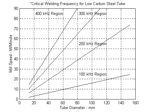
Figure 1
can be used to determine the best welding frequency for a particular mix of tube products and mill speeds. It should be made clear that no claim is made that good welding cannot occur at frequencies that would put the process in the Transition or Electric Power Mode. Indeed many systems have operated in these modes for long periods of times. However, our analysis will show that a more consistent quality and significantly better efficiencies are achievable in the Thermal Mode.
In order to validate these results experimentally the same tube was produced at three different weld or mill speeds and several different welding frequencies ranging from 100 kHz to 400 kHz. Weld area set-up and "VEE" temperature were held constant the power required to achieve this temperature was recorded. Heat affected zone widths were also measured in each case. In each case careful measurements of required power and heat affected zone widths were in close agreement with the above analysis. More detail on these results is available elsewhere2.
Beyond “Critical Frequency"
Taking the above analysis a step further, we can examine the temperature distributions along the edge of the VEE in a direction normal to the edge (CIRCUMFERENTIAL). We can also examine the power delivered to the VEE at the same point as a function of frequency. These results allow us to determine the tensile strength profiles as a function of temperature and welding frequency. It is the tensile strength distribution that determines the ability of the metal adjacent to the melted layer to effectively squeeze out all of the melt.
We first look at a 50 mm diameter by 2 mm wall thickness tube welded at 150 meters per minute. Figures 2 and 3 show the temperature distributions from the beginning of the VEE to the closure point at 200 kHz and 400 kHz respectively. There is a clear temperature gradient in the 400 kHz graph all the way to the VEE apex. At 200 kHz, the temperature at a point 80 percent down the VEE is the same as at the apex. Heating beyond the 80 percent point represents additional wasted energy. It also raises the temperature of additional metal into a dual phase range containing both ferrite and austenite. The larger the volume of steel in this temperature range passing through the weld squeeze rolls the higher the probability of defects caused by “worked ferrite".
Figures 4 and 5 represent the temperature and power distribution right at the apex for the 50 mm by 2 mm tube at 200 kHz and 400 kHz respectively. Notice should be taken of the slope of the power curve as the closure point of the apex is approached. Power is still being injected at a much higher rate at 200 kHz than at 400 kHz and this is evident by the behavior of the temperature on the same graphs. A considerable amount of excess heat enters the strip at a greater rate thereby destabilizing the process.
What we are really seeing here is the difference between the “Thermal Mode"
and the “Electric Power Mode". Much more power is required at the lower frequency thereby affecting the efficiency considerably. Figures 6 and 7 show the temperature distribution at the apex as a function of frequency from 100 kHz to 600 kHz. Again, notice how much further into the wall the highest temperatures move at the lower frequencies. This represents wasted energy and unwanted higher temperatures in the steel that is about to be “hot worked".
To further emphasize the effects of the welding modes, we also examined a 150 mm by 8 mm steel tube being welded at 40 meters per minute. Figures 8 and 9 represent the temperature distributions along the VEE at 100 kHz and 400 kHz. The family of curves at both the low and high frequencies are quite similar. Both cases are in the “Thermal Mode". Figures 10 and 11 show the relative power and temperature distributions at the apex and again at 100 kHz and 400 kHz. From what we have already seen, these are both in the “Thermal Mode" and parameters are behaving as described in Eq. 6 above.
It is also instructive to examine the tensile strength distributions at the VEE apex for both tube sizes as a function of welding frequency. Figures 12 and 13 show these distributions for the 50 mm and 150 mm diameter tubes respectively. It is important to note the location of the “knee" of these curves as the frequency changes. The tensile strength of the steel adjacent to the melt layer as a function of distance away from the melt layer is considerably higher at the higher frequencies. This is a clear indication of how deep into the edge or wall of the tube distortion will occur due to weld upset forces.
Finally we look at the same two tubes for power delivered by the welder as a function of frequency. Note the linear relationship corresponding to Eq. 8 for lower frequencies in Figure 15 for the smaller tube, and the square root relationship in Figure 14 at all frequencies corresponding to Eq. 6 for the larger tube. Again the distinct difference between the “Thermal Mode" and The “Electric Power Mode".
Conclusions:
When designing and planning for a modern high frequency tube and pipe welding system one must BEGIN with the END in mind - that is a consistent high quality forge weld. The above analyses can serve as the direction that must be taken in order to optimize weld quality. The relationship between weld speed, weld frequency and tube or pipe diameter is now clearly understood.
As the high frequency welding of tube and pipe becomes more of a science and less of a phenomenological process, producers should derive many more benefits from their welding systems. With an understanding of the key relationships between the process parameters and product quality, scrap should be significantly reduced and more tonnage of high quality products produced thereby improving return on investments.
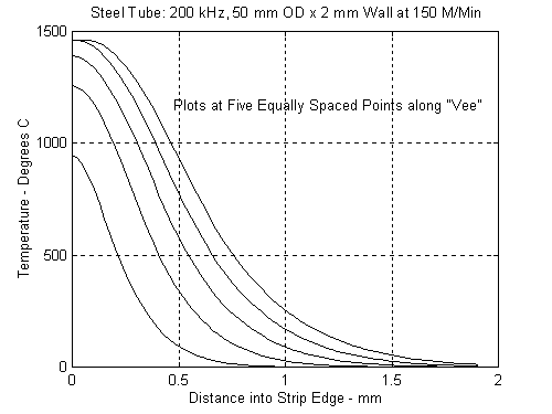
Figure 2
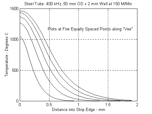
Figure 3
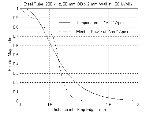
Figure 4
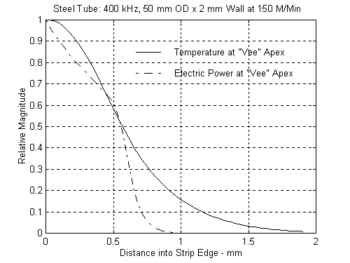
Figure 5
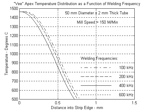
Figure 6
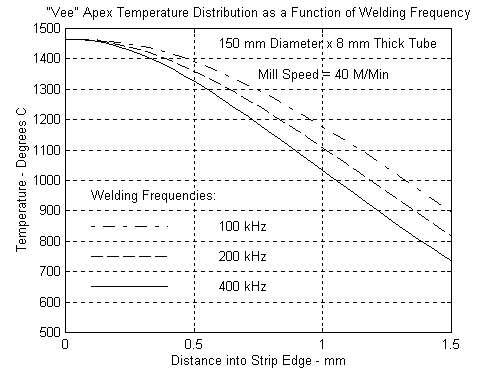
Figure 7
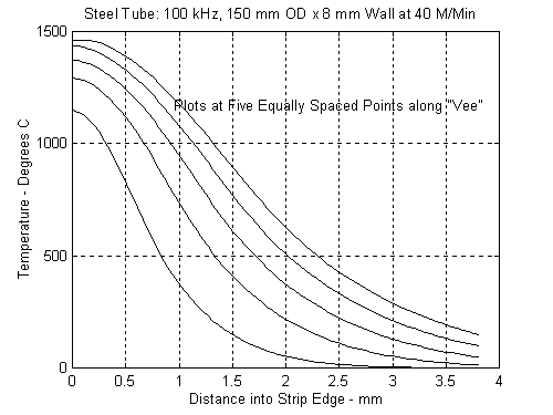
Figure 8
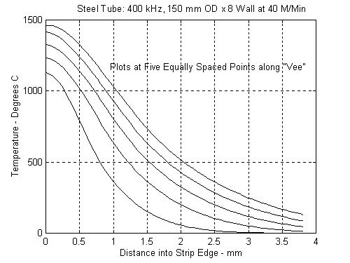
Figure 9
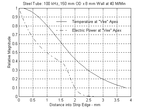
Figure 10
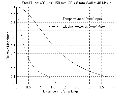
Figure 11
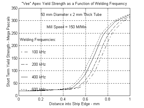
Figure 12
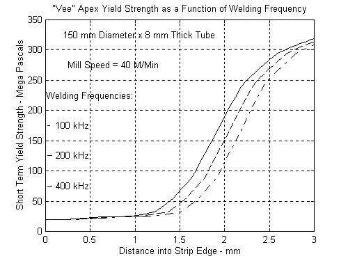
Figure 13
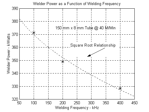
Figure 14
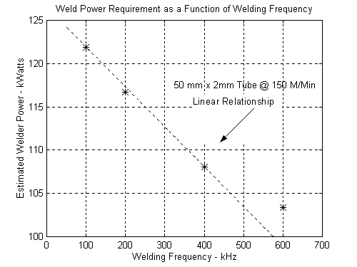
Figure 15
1Scott, P. F., and Smith, W.;"A Study of the Key Parameters of High Frequency Welding, Part II"; Transactions of Tube China '95; ITA Publication
2Scott, P. F.; “The Effects of Frequency in High Frequency Welding"; Transactions of Tube 2000, Toronto; ITA Publication
For more information, please contact :
Thermatool Corp.
East Haven, CT, USA
Tel: (203) 468-4100
Fax: (203) 468-4281
Email.
Contact. Paul Scott, Vice President, Technology
|