Manufacture of Laser Welded Composite Tubes
by
Dr.-Ing. Bruno E. Buluschek,
SWISSCAB SA, CH-1462 Yvonand, Switzerland
Composite tubes combine the benefits of metal tubes with those made of plastic, even new properties can be reached.
An original manufacturing process offers innovative solutions for a variety of applications: anytime the grade of the polymer,
the metal or the respective layer thicknesses can be changed or adapted.
I. Composite tube
In this context, a composite tube should be understood as a tube composed of 3 functional layers:
- an inner tube, extruded from a polymer chosen for specific properties
- a metallic layer, formed and butt-welded from a strip of aluminium, steel or copper
- an outer tube or sheath, made from a convenient thermoplastic material.
As these 3 layers have to behave like one, 2 thin layers of an adapted adhesion promotor assure the desired strong bonding. Finally, a composite tube can be considered as a 5-layer tube, see fig. 1.
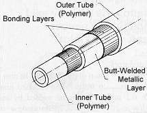
Fig. 1. Triple layer tube
II. Properties
The manufacturing process detailed further down, offers a tremendous freedom for the tube design. The free choice of polymers, of metals and of the thickness relation polymer-metal allows to realise basically:
- a metal tube with polymeric layers inside and outside
- a plastic tube incorporating a metallic layer
- a new tube featuring more benefits than those obtained by adding those from metal tubes to those of plastic ones.
Compared to either metal or plastic tubes, the following properties can be reached or fine-tuned:
- corrosion resistance
- gas permeation (02, fuel, alcohol)
- anti-electrostatic behaviour (electric conductivity)
- fire resistance
- weight
- noise/vibration damping
- connecting technique (heat welding of outer polymer - tight connection by plastic deformation of the metallic layer using the polymer as an elastic seal - crimp connection - tightness by elastic deformation of the inner polymeric layer, etc.)
- installation technique (composite tubes can be designed to bend easily and to stay in their bent form without tempering)
- taylor-made resistance to lateral deformation, to bending to internal pressure
cost optimised design
- smooth inner surface retards turbulence and allows for a high flow velocity without creating noise
- thermal insulation / anti condensation
- rodent protection
- electrically insulated
- more to be found - this is a new technology.
Up to now, composite tubes are increasingly used in sanitary installations for hot and cold drinking water as well as for floor heating. Here their success is based on the combination of the flexibility of plastic tubes with the oxygen permeation tightness of metal tubes while still offering easier installation and a more comfortable connecting technique than either metal or plastic tubes.
Applications under development are:
fuel ducts for cars and aeroplanes (hydrocarbon diffusion tightness, bendability, fire resistance, connection, etc.)
OPGW (tube for optical fibres installed in the ground wire of high tension aerial power lines)
coaxial and power cables.
III. Manufacture
Advantageously, a composite pipe is manufactured in a one step process, see fig.2. Exceptionally, the inner tube can be produced separately, then e.g. radiation crosslinked in specialised site and finished in a second step.
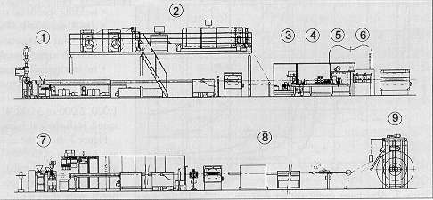
Fig 2. Triple layer tube production line.
Pos. 1 in fig. 2 indicates the extrusion group for the inner tube. Best bonding will be achieved when the main layer and the glue are coextruded through one extrusion head. The outer diameter of the tube is calibrated by a vacuum trough, the inner diameter is either measured by ultrasonic sensors or, more commonly, assured by either a gravimetric dosing device on the main extruder or by a metering melt pump. The extruders are designed to process all common thermoplastic polymers.
Pos. 2 shows the supply of the metal strip, composed of a double, eventually driven pay-off, a (nearly) automatic laser transverse welder for butt-welding the end of an empty coil to the beginning of the new and full one [1]. This welder is followed by an automatic strip-accumulator which allows an uninterrupted composite tube production of unlimited length.
In Pos. 3 the strip is calibrated. Commercially available metal strips are not very precise in width, the borders may have been damaged during transport; this is why the strip has to be cut on both sides in order to bring it to a precise width with perfectly shaped edges. A further benefit of this station is that the strip width may be adapted any time to small changes in the dimension of the inner element (tube, cable)
In the forming bench, pos. 4, the metal strip is first conditioned and precisely positioned and then formed into a tube, using a computer assisted design for the form rollers, (see special paper given during this conference) and their arrangement. For a diameter - to - wall thickness ratio higher than 60, the stations are not driven. Due to the chosen welding process (laser), the precision and stability of the forming bench must be very high: the gap between joining strip edges must be kept constant within 0 and 0,03 mm, assuming a 0,15 mm metal strip. The position of the seam must be stable within ± 0,05 mm. Care has been taken that this precision does not get lost when tools have to be changed for the production of another tube dimension.
Pos. 5, Welding. After a serious comparison of available welding systems, laser welding has been chosen. The principal reasons for this choice have been:
- contactless (optical) welding process
- metal strips down to 0,1 mm can be industrially welded
- without any adaptation can be welded:
- steel
- stainless steel
- aluminium (weldable grades)
- copper (weldable grades)
- tin coated steel
- zinc coated steel
- aluminium plated steel
extremely low thermal solicitation of the product. In most cases the product is not even warm when touched just after welding. An 0,2 mm strip can be welded by an absorbed power as low as 20 to 80 Watts, corresponding to an introduced energy of 0,00006 kWh/m per meter of welded tube. This effect is specially important as soon as heat sensible products are below the welding point.
real fusion welding
weld nearly invisible
welding speeds up to 30 m/min have been realised
a weld seam following control through the laser optic (this means at the point where the precision is needed) is possible
smooth surface inside and outside the tube
no intrinsically wearing elements
The laser welding equipment consists of
1. the laser source having an output power of 500 W (pulsed), 1000, 2000 or 3000 W (CW), depending on the demands in speed, wall thickness and the material to be welded. Fig. 3 shows the absorption coefficient for different metals as a function of the wave length of the light. At least for thin metal strips (greater than 0,5mm) this coefficient determines the power necessary for a given job. Due to the high reflection, e.g. copper needs more than a tenfold the power of steel.
For bigger wall thickness this effect decreases strongly due to multiple light absorption in a deep welding channel. The power density threshold for this effect is about 1 x 10⁶ W/cm2 for steel and 4 x 10⁶ W/cm2 for aluminium.
Starting from a 2 kW laser, a closed loop cooling system is recommended.
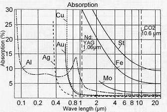
Fig. 3 Absorption coefficient for different metals at laser wave lengths [2]
2. the lightwave guide, connecting the laser source with the welding optic. This flexible wave guide may be up to 40 m long and gives a very welcome freedom in the arrangement of the elements.
3. the focusing optic. This element can be adjusted in 3 axis using small step-motors. The digital control allows to memorise set-up for different products. One of these motors is controlled by the seam following logic. Temperature sensors permit to minimise reflecting light by choosing an optimal attack angle. An eddy-current seam quality verification completes the welding station
Pos. 6: Compactation: The inner element of a composite tube will always have dimensional tolerances. The inner diameter of the metal tube formed and welded around the inner tube is chosen in a way that even peaks in the tolerance of the inner tube will not interfere with the tube forming and welding step. The layers of a composite tube have to stick strongly together, no (air) gap can be tolerated. Consequently the metal tube has to be compacted to the minimum diameter within the tolerance of the inner tube. This is done by the compacting bench.
The number of individual stations depends on the amount of diameter reduction required. Normally, these stations are not separately driven but prepared for drives for certain conditions.
The tube is now finished by coextruding, the outer adhesion promotor together with the outer sheath, Pos. 7. Again, this sheath can be chosen among the whole variety of thermoplastic polymers, crosslinkable or not. The extrusion group is controlled by an X-Y diameter gauge. After printing the desired identifications on the tube, it can be either spooled on a drum, Pos. 9 (dia. ~ less than 40 mm) or cut to length, Pos. 8.
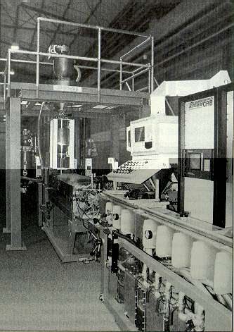
Fig 4. Triple layer tube production line
IV. Summary
To our knowledge, this is the first time that a manufacturing process is commercially available being able to industrially butt-weld metal tubes with a wall thickness down to 0,1 mm.
A composite tube can be designed according to functional needs without the limitations imposed by the welding process. Nearly any property profile of a tube can so be realised in very cost efficient way, due to the free choice in polymers, metals and their dimensions.
Lit.:
[1] Buluschek: « Splicing Metal Tapes by Laser Welding » Journal « Wire Industry » April 1994
[2] Jan L. C. Wijers: « Nach CO2 nun Nd: YAG Laser für Blechbearbeitung »
Journal « Technische Rundschau », Bern
TR Transfer nr. 112 1996
Further information:
SWISSCAP SA
Attn: Mr. Bruno Buluschek
Fax. +41 24 4300124
Email.
|