TUBE AND PIPE THREADING ADVANCEMENTS
FOR STANDARD AND PREMIUM JOINTS
By Paul Znidar, PMC Industries, Ohio, USA
The methods for generating high quality, cost effective, leak-proof threads on a production basis have evolved over time. The technologies employed by the machine tool builders to achieve this goal have likewise evolved. During the 1920's, receding dies made from tool steel or high speed steel represented the state of the art. These simple machines gave way to more automated and therefore more productive high speed steel tooled threaders in the 1940's. Carbide tooled pipe threading machines were introduced in the 1960's and provided the platform from which today's Computer Numerically Controlled (CNC) threaders were created.
The developments and design changes of today's CNC threaders were driven by customers' demands for improved product quality and the spindle speed increases needed to make use of improved tool materials. In the 1920's, a pipe threading spindle that rotated at 15 meters per minute (MPM) was considered state of the art. Today's CNC machine spindle speeds are a ten-fold increase over their predecessors and achieve threading speeds in excess of 150 MPM. Further developments in machine lubrication, and tooling and surface treatment technologies will treble again today's speeds.
Technological improvements are evident in all aspects of today's threading machines. Electrical controls have lept forward from the slow, rather unreliable contacts found in A.C. relays to Programmable Logic Controllers (PLC), electromechanical motion controllers, Computer Numerical Controls (CNC) and the PC supported WindowsÔbased Open Architecture in use now and for the forseable future. These control improvements were made possible in part by the speed and reliability upgrades as contact-type limit sensors gave way to faster non-contact type sensors.
Electric motor and drive technologies were not forgotten in the push for faster, more accurate threading machines. Previously D.C. motors and drives were used in most applications where steady torque and/or horsepower were needed. D.C. systems performed adequately but required frequent maintenance. The bushes in DC motors required regular replacement to keep the motors functioning properly.
The development of AC vector technology provided a viable alternative to the DC drives. The AC vector drives provide improved response and reduced maintenance demands due to their brushless design. When these drives are operated as a closed-loop system, the quick response times and speed/position feedbacks translate into nearly constant spindle speeds, regardless of the loads applied.
There are two basic approaches to pipe threading; the first is to hold the tooling stationary and rotate the tube. This approach is used primarily in lathe type machines. The second method is to hold the pipe stationary and to rotate the tooling. While arguments can be made regarding the benefits of either approach, the following advantages are found in tool rotating machines.
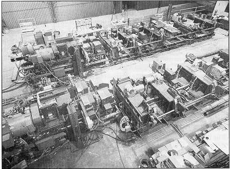
Figure 1. Overall view of two single end line model 471 CNC pipe endfinishing units.
Tool rotating machines –
- Allow for higher cutting speeds and easier, more controlled speed changes during the machining sequence.
- Experience less vibration as the rotating members are dynamically balanced as a part of their manufacturing sequence. High speed rotation of hooked or bowed pipe induces substantial vibration at the tool/pipe interface. Vibration adversely affects product quality, dimension stability and surface finish.
- Reduce the wear on the associated tube handling equipment. This reduces maintenance requirements and increases production hours.
- Increase throughput because spindle rotation is not stopped after each pipe.
- Use less energy as less horsepower is needed to rotate tooling versus pipe.
- Operate at lower noise levels as abatement measures are designed into the machines and handling equipment.
The balance of this article compares the operation of PLC based and CNC based, tool rotating machines. The picture below highlights the differences in the gear train schematics for a conventional, receding die type threading machine with PLC control and the same type of machine with CNC control.
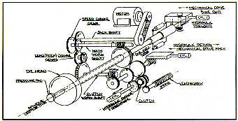
Figure 2. Gear train schematic - lead screw feed, 60 - 140 mm OD carbide threader.
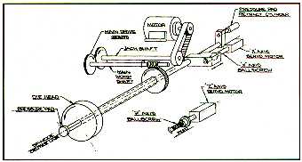
Figure 3. Numerically controlled 60 - 140 mm OD carbide threader.
It is clear from the schematic that the CNC threader has far fewer moving parts and is mechanically simpler than its conventional, PLC based counterpart. This simplicity makes for a machine that is easier and quicker to set-up and that requires less maintenance. Further, the CNC unit is equipped with coding for self-diagnostics that assists the operator in troubleshooting the equipment. Reduced set-up and maintenance times translate into increased operating time that increases throughput on an annual basis.
The conventional and CNC threading machines employ wedge actuated tool holders to position the tools at the correct radial position throughout the cut length. At the end of the threading stroke, the tools are “collapsed" completely out of the thread, the spindle housing returns to its home position and the tool blocks return to their start positions. On conventional machines, all of the cutting tools move simultaneously and their total radial stroke is determined by the length and angle of their actuating wedges. Conventional threaders employ uni-directional wedges to perform taper turn and thread operations for standard, pipe end geometries as are found on API, ASTM, BS, DIN and JIS product types.
CNC threading machines use two sets of wedges that are bi-directional and are servomotor and ballscrew driven. These bi-directional wedges permit complete, pipe-end finishing (face, chamfer, ream, turn and thread) in a single chucking. Bi-directional wedges also enable the CNC threader to generate the seal surfaces found on most premium joints in the market today. Servo actuation of the X and Z axes permits “multiple pass" capability so that an unlimited number of threading passes can be made on the machine. Progressive, deeper, threading passes reduce productivity but make possible the complete, automatic machining of difficult end geometries and high strength materials such as 13CR, P-110 and V-150. Multi-pass threading reduces tool and chip loading, increases tool life and improves product taper and stand-off characteristics.
As stated above, all of the tool blocks move simultaneously on conventional threaders. Due to the bi-directional wedges found on the CNC machines, these tools are positioned in sets. A matched set of three (3) chasers is mounted on different tool blocks than the face, chamfer and ream tools. The chasers are generating threads while the remaining tooling is not in contact with the workpiece. Similarly, when the face, chamfer and ream tooling is cutting, the chasers are positioned away from the pipe.
Lastly, the precise digital control of the CNC, through the servo-ballscrew actuator, allows for a deburring option in either standard or premium joint threading sequences. The deburr move reduces the burr on the starting thread to approximately 0.05mm.
Advances in control technology are initiating the move away from the canned capabilities of PLC's and CNC's to industrial hardened laptop computers and WindowsÔbased operating systems. As open architecture options become more cost effective, machine tool builders will be able to maximize machine controls by equipping them with specific use hardware and software for their exact application. This will allow for further integration of individual machining stations onto LAN's or WAN's that are controlled by a host computer.
During the evolution of threading and end-finishing machinery into the ultra fast, flexible and dimensionally stable machines of today, control systems have undergone a similar transformation change. Today's equipment utilizes components that would have been unheard of a few years ago. Man machine interface (MMI) software allows the modern machine operator to precisely control each element of the production cycle. From the speed of incoming raw material transfer to final spindle speed and feed rate of the completed work piece the operator is in complete control. We are truly in the midst of the information age. The use of MMI software offers date acquisition capabilities that can provide tracking of a product's quality, certifiable documentation of a machine's calibration and rate of production details to the second.
The current approach to machine set up and operation provides simple menu driven selections for product type, element configuration and material choices. CNC part programming is accomplished using parametric programming techniques. With this advanced method of programming, the logic and structure of the base program is maintained throughout all product size and configurations. The selection of a product size and type loads specific variables into the controller's memory registers. The parametric program accesses these variables during the execution of the production cycle insuring that each step of the program is identical for all size and type product. Using this method of programming, additions to the part library require only the generation of the unique variables that describe the product. The logic programming does not require modification.
Today's threading and end-finishing machines are vastly more flexible and more productive than machines of a few years ago. Continued advances in machine, control and inspection technologies may well lead to the unmanned, end finishing facilities of tommorow.
Paul Znidar is an engineer and is the International Sales Manager at PMC Industries, Inc., 29100
Lakeland Blvd., Wickliffe, Ohio USA 44092. PMC is a full-line manufacturer of pipe and coupling finishing equipment, gages and inspection instruments.
For more information please contact:
PMC Industries, Inc
Paul Znidar
Tel. 440-943-3300
Fax. 440-944-1974
Email.
WEB Site. http://www.pmcindustries.com
|