Highly Improved Function and Productivity
for Tube Bending by CNC Bender
by
Makoto Murata
Department of Mechanical and Control Engineering
The University of Electro-Communications, Tokyo, Japan
and
Tadao Kato
Nissin Precision Machines Co., Ltd. Tokyo, Japan
A new flexible tube bending method which is controlled by computer, has been invented and named MOS bending by the author.
The new CNC bender is able to be built and changes image of the conventional tube bender. The bender does not need replacing dies when changing bending radius but needs only changing an easy bending program. Bending radii and angles can be easily adjusted by putting a tube through the die.
The cross-section deformation of tube and the decreasing of tube wall thickness can be avoided. There are many benefits on the MOS bending. The mechanism, characteristics, benefits, bending program and some examples of products of the MOS bending are presented in this paper.
1. Introduction
Bent circular tube products are employed in manufacturing many kinds of products such as fluid arrangements, furniture, transport apparatus, and mechanical parts, as required for reduction of production cost and weight.
Press bending, stretch bending, draw bending and other various bending methods have been developed and are used depending on operation efficiency and other requirements. However, conventional bending methods can not meet demands on precision in some cases, due to the tube roundness and the relatively flat cross-section of bent tubes. Their bending dies must be changed depending on the bending radius and the outside diameter of tubes to be bent. Those methods that can be used to bend them, are suitable only for long production runs in limited sizes, but not for short production runs in a variety of sizes.
Therefore, the author has invented a new flexible penetration bending method and named it the MOS bending method, which is controlled by computer and is available for various bending radii with high precision. The new CNC bender is able to be built and changes the image of the conventional tube bender.
2. Benefit of CNC Tube Bender Using MOS Bending Method
The CNC tube bender using MOS bending method has many epoch benefits unlike conventional tube benders as follows;
- Bending radius can be easily set.
Unlike the conventional bending by pressing a tube, rolls or bending dies are
not used any longer with this model so that desired radius can be specified
freely.
- Deformation ratio of the tube cross section is minimized. Unlike the conventional type, the bending section is securely guided by the die so that accurate roundness can be obtained on the cross section.
- Bending radius can be continuously changed.
Radius and bending directions(X/Y) can be easily controlled by the computer.
- Versatile bending forms are available.
Bending at an angle of more than 180?, large-radius bending, and spiral- form
bending are available now.
- Sophisticated bending form is obtained.
As there is no difference in levels in the bending section, a smooth and even
finish can be achieved.
- Operability of various functions is improved.
Inputting the coordinates of a bending section is also available besides
ordinary inputting. Quiet environment is ensured because of motor-driven
operation at high speed.
3. CNC Tube Bending Machine Based on MOS Bending Method
3.1 MOS Bending Mechanism
|
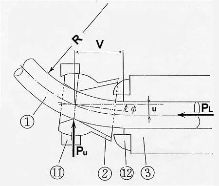
M = PU � V + PL � u
1 - Tubular workpiece, 2 - Bending die, 3 - Guide cylinder
11 - Spherical bearing, 12 - Jig for control of die inclination
Fig. 1 Principle of MOS bending method
|
|
The principal parts of the bending mechanism are shown in Fig.1. The structure is very simple. The basic principle of the MOS bending method is explained as follows:
The relative distance between the center line of the guide cylinder (3) and the center of the bending die (2) is called offset u. A tubular work piece (1) is penetrated into the die from the guide cylinder by axial force PL, then it is bent as shown in Fig.1. For this machine, the distance (called approach V) between the exit of the guide cylinder and the center of the bending die is not changed. In the neighborhood of the bending die, the tube is pushed by the bending die as shown by the arrow in Fig.1. The extrusion load Pu depends on the magnitude of the offset u. At this time, a bending moment M = (Pu � V + PL � u) operates on the tube which is bent. The die's position is moved continuously by AC servomotors.
3.2 CNC Tube Bending Machine
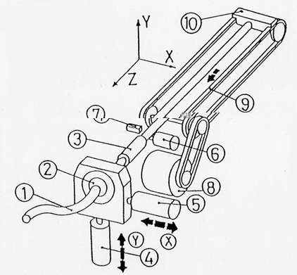
A sketch of the CNC bending machine is shown in Fig.2.
|
1 - Tubular workpiece, 2 - Bending die, 3 - Guide cylinder
4 - AC Servo motor for control of X-axis,
5 - AC Servo motor for control of Y-axis,
6 - Rotary encoder for measurement of forward tube length
7 - Approach switch, 8 - Motor for forming of tube,
9 - Chain for forwarding of tube,
10 - Plate for forwarding of tube
|
Fig.2 Main components of CNC Bender
|
|
The AC servomotors are controlled by the computer and they control the position of the bending die. The bending is carried out as follows:
- A tube (1) is inserted into the guide cylinder (3).
- When the motor (8) for tube forming is activated, the tube is pushed toward
Z axis by the plate (10) for forwarding the tube. The plate is fixed to the chain
(9) forwarding the tube, and the tube is penetrated into the die (2).
- The die is shifted continuously toward X and Y axes by the AC servomotors (4), (5).
Once a tube is bent to a certain radius, the die is shifted to the position of offset u which depends on the radius R (the relationship between the offsets and the radii is shown in Fig.4 ). When a tube is bent to a certain angle, the tube length is measured by the rotary encoder (6) and the tube is continuously penetrated into the shifted die. The bending radii can be changed at our option and three-dimensional bending is realized. When the top of the tube is sensed by the approach switch (7), the bending is begun. Figure 3 shows the control system of the CNC tube bending machine and the system of the machine is controlled by personal computer A photograph of the trial CNC bending machine which has been built is shown in Photo 1.

|
Fig.3 Control system of CNC bender
|
|


|
Photo 1 CNC bender using MOS bending method.
|
|
3.3 CNC Bending System
The bending radius R of the tube is decided by the magnitude of offset u. The relationship between the offsets and the bending radii is shown in Fig.4 as a parameter of material type.

|
Fig.4 Relationship between offset u and bending radius R
|
|
The relationship can be obtained by bending experiments. The flexural rigidity, Young's modulus and other material properties of the tubes vary with changes of materials and dimensions of the tubes. Therefore, the bending radius R varies even though the offset u does not change. But this bending machine can bend the tubular work piece into a certain bending radius by adopting a suitable relationship of u and R for the tube, even though the tubular material or dimensions change.
The relationship between the penetration lengths of tubes Wt and the bending angles  t is shown in Fig.5, when the bending radii change. t is shown in Fig.5, when the bending radii change.

|
Fig.5 Relationship between penetration length of tube and bending angle.
|
|
In the figure, t is almost proportional to the penetration lengths of tubes Wt. But the bending radii of the tubes which have been bent by this bending method, are not equal to the set bending radii in part. These parts of tubes are called incomplete R parts. Because, the tube is being penetrated into the die, while the die is moved toward the setting position.
The software for the CNC bending machine is explained as follows. The shape of the bent tube is decided by straight parts ln, bending radii Rn, bending angles n and bending directions  n on the X-Y plane as shown in Fig.6. and Fig.7. The bending directions are explained in Fig.7. n on the X-Y plane as shown in Fig.6. and Fig.7. The bending directions are explained in Fig.7.

|
Fig.6 Example of tubular bending deformation.
|
|

|
Fig.7 Example of bending direction.
|
|
The coordinate axes for input are drawn with solid lines, and the bending direction for n-th bending is illustrated. The straight part of tube Pn-1-Pn is overlapped upon the X axis of the input coordinate axis by revolution around the point Pn-1. Then, as shown in Fig.7, the bending direction of n-th bending on the Y-Z plane is calculated as,
n=n-1 + n n+1 - n-1 n-2
The n-th bending direction can be gotten from the (n-1)-th bending direction. In the bending method, Rn, n, ln and n are represented by functions as following
equations. Therefore tubes can be bent to the required bending forms by controlling uxn, uyn and Wn corresponding to optional Rn, n, ln, and n
Rn= f (uxn, uyn)
n= f (uxn, uyn ,Wn)
In= f (Wn)
n= f (uxn, uyn)
Where,
uxn, uyn = X axial and Y axialcomponents of offset for the n-th bent part
Wn = forwarded tube length toward Z axis for the n-th bent part.
But, if the material and dimensions of the tube are changed, the bending radius and the bending angle may change even if uxn, uyn and other figures do not change. Functions on Rn and n vary with the material and dimensions of the tube.
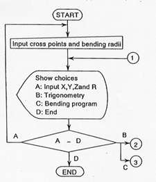
The flow chart for inputting the bending data is shown in Fig.8. Cross points of two straight parts, bending radii, and the first bending direction are input first, and secondly appropriate offsets and penetration lengths are calculated by the computer. The aforesaid equations which were obtained from experiments are entered into the computer.

|
Fig.8 Flow chart of input data for MOS bending
|
|
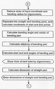
The outline of the bending machine movement for carrying out the bending is shown in Fig.9 as a flow chart.

|
Fig.9 Flow chart of control for MOS bending machine
|
|
The bending data, which was obtained from the program in Fig.9, is fed into the computer. The motor for the tube forming is activated and the tube, which has beenn set in the bending machine, is pushed toward the Z axis. When the tube is penetrated into the die, the microcomputer transmits pulses to the AC servomotors for control of the X and Y axes.
The number of pulses depends on the offset magnitude. Then the AC servomotors are activated and the die is shifted. During the tube bending process, the penetration length of tube is read by the rotary encoder, and the die is fixed at the ordered offset position while the necessary length of tube is penetrated.
After the required tube length has been pushed out from the die, AC servomotors are again activated and the die is shifted to the next ordered offset position for the following bending. These procedures are repeated in regular order. After the bending has finished, the motor automatically turns off.
This bending machine is controlled by a CNC computer which is made by Mitsubishi Electronic Corporation.
4.Bending program and Examples of bending products
4.1.Bending program of bending product
The bending system and software, which are explained in the former chapter, are input into the computer of the new CNC bending machine. The users can easily produce complex bent tube products, which can not be produced by the conventional CNC bending machine, by only inputting an easy program corresponding to the bending.
One example of a bending program, which can bend the setting shape with the new CNC bending machine, is indicated as follows;
BENDING PROGRAM
| G01 | L200 | R40 | T90 | P90 | F25 | E25 |
| R130 | T90 | P90 | | | | |
| R40 | T90 | P180 | | | | |
| R40 | T90 | P180 | | | | |
| R130 | T90 | P90 | | | | |
| R40 | T90 | P90 | | | | |
| M02 | | | | | | |
Fig.10 Example program of circular tube
products using MOS bending machine
|
|
Figure 10 shows the bending program which can produce bent tube products as shown in Photo 2. One line of the program contains orders to operate one tube bending process and the bending program is explained as;
- G01 means normal operation,
- L200 means a 200mm straight length,
- R40 means a 40mm bending radius,
- T90 means a 90 degrees bending angle,
- P90 means a bending direction and,
- F and E mean moving speeds of the die.
- M02 of end line is the ending of the bending operation.
When 6 bending processes are operated on the tube as shown in Fig.10, the bent product, which is shown in Photo 2, can be easily manufactured by the new CNC bending machine.

|
Photo 2 Example of circular tube product using above easy program
|
|
The straight length(L), bending radius(R), bending angle(T) and bending direction(P) are input into the computer of the new CNC bending machine to bend the tube into various shapes, using the easy bending program.
4.2 Examples of bent tube products
Bent tube products which have not been able to be manufactured by a conventional CNC bending machine, can be easily manufactured by the new bending machine based on the MOS bending method. Some examples of the bent tube products are introduced as follows;
(1) Chair
Chairs, which could be manufactured by the new CNC bending machine, are suitable for human beings as shown in Photo 3.

|
Photo 3 Comfortable chairs for human being
|
|
The shape of the human body is very complex and three dimensional. Therefore, the chairs have to be made to fit to the complex and three dimensional human body shape. When chairs of complex and three dimensional shapes are made by a conventional CNC bending machine, many complex shaped dies are needed. The bending process is very difficult and many days are needed for preparing, arranging the dies and the bending process. But, if the new CNC bending machine is used to make complex shaped chairs, only easy bending programs are needed to be input into the computer. The complex shaped chairs can be easily produced after a little trial bending.
(2) Exterior
The actual bent tube examples which make good use of the characteristics of three dimensional, flexible and fine bending are shown in Photo 4.


|
Photo 4 Three dimensional, flexible and fine exterior
(a) Monument (b)Fence
|
|
Various exteriors have been made of tubes by the new bending machine in Japan such as a monument (Photo a) and a fence (Photo b). If the shapes in Photo 4 would be manufactured by a conventional bending machine, various shaped dies would be necessary for fitting the shapes and many days would be necessary for arranging the die shapes and trial bending. Complex three dimensional shapes and designs are demanded for exteriors. But the new bending machine can easily answer the demand for short production runs in a variety of sizes at low cost. If the bent tube shape is not to the designer's taste, the shape can be easily changed by changing the bending program of the new bending machine.
(3) Interior
Photo 5 shows a vase stand as an example.

|
Photo 5 Designable vase stand
|
|
The new bending machine has no limit for the designers' request about shapes as compared with the conventional bending machine. Therefore, designers can display their ability to develop and make various shaped bent tubes.
(4) Refrigerator
Photo 6 shows the refrigerator tube of a radiator.


|
Photo 6 Refrigerator tube of radiator
(a) Before setting fins (b)After setting fins
|
|
Fig(a) shows the one before setting fins on the tube and Fig(b) shows the one after setting fins on the tube. The flatness of the cross section of the bent tube is within 1% using the new bending machine. Therefore, many fins can pass through the bent tube smoothly and can stick closely to the bent tube. The thermal efficiency of this radiator is superior to the conventional one.
(5) Others
Some tubular handles of bicycles are bent by the new bending machine. Because, tubular handles must be manufactured to fit the weight, stature, arm length and other conditions of the cycle racers. The tubes which are bent by the CNC bending machine, are used in the refrigerator of the atomic pore generator. Because, the decreasing of the wall thickness on outside of the bending can be prevented. The bent tubes are stronger than the tubes which are bent by the conventional bending machine, at intensity and high pressure.
Four different dimension types of the new CNC bending machine are prepared for the changing of the tube diameter and the largest bending machine can bend 114mm diameter tube.
Conclusion
Many advantages and mechanism of this CNC bending machine are presented in this paper. More than forty new CNC bending machines based on the MOS bending method have been sold in Japan, Germany and the US.
The CNC bender will have to add high values to the bending operation with a variety of functions to meet the needs of the times. We hope that the difficult tube bending can be practiced by this new CNC bending machine and we wish to further contribute to the development of tubular bending.
References:
- Takahashi, A.:JSTP(Japan Society for technology of Plasticity) 106th Symposium Text, (1986)17.
- Ochiai, I.: J. of JSTP 23-255(1982),290.
- Takagi, R. : J. of JSTP, 23-255(1982),282.
- Yamatake, H. : J. of JSTP, 10-103(1969),618.
Further information :
|