Fine and Productive Tube & Pipe Cutting by Tip Saw System
NAKATA MFG. CO., LTD. Technical Department
Iwao Nakata, Fusatsugu Abe, Hiroyoshi Kato
1. Introduction:
Recently, the production ratio of ERW tube has been increased in total tube production
owing to the development of cold forming technology, welding technology and NDT technology.
In the ERW tube production process there is a movement of Production speed up, High
efficiency, Less process, High quality of material and Expansion of application, etc., but in the
flying cutoff machine as its final production process we cannot say that such requirements can
be fulfilled.
As the typical flying cutoff machine, there are Low speed TCT cutoff saw, Friction saw, Press
cutter, but they have their merits and demerits respectively. Especially in Friction saw and
Press cutter, the quality in cut surface cannot be accepted by the market, and they need a
large scale of finishing process which is the largest issue.
On the other hand, Tip saw brazed with a carbide alloy, which has been started to be produced
domestically for woodworking in about 30 years ago, has improved its performance remarkably
owing to the improvement of carbide alloy and the progress of manufacturing technology of
low strain of mother plate and has expanded its application in the steel tube industry since
about 10 years ago.
In this paper we are introducing a recent technical tendency of TCT Flying cutoff saw applied
in the ERW tube production process.
| |
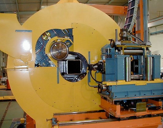
Fig.1 High speed TCT Cutoff Machine
|
|
2. Existing TCT cutoff saw:
There are following major 3 kinds of TCT cutoff machine in the market currently:
1. Cross type with one piece of TCT blade:
This type is mainly used for stationary type cutoff machine, but has a demerit of short life of
saw blade, because the sticking out distance from flange to point of tip is large, two sides of
tube are simultaneously cut and it is difficult to discharge the chips.
2.  - Control type with multiple pieces of TCT blade: - Control type with multiple pieces of TCT blade:
Multiple pieces of TCT blade are located on the same disc plate, the sticking of TCT blade
into the tube to be cut is carried out by a rotating arm mechanism and the cutoff, thereafter,
is carried out by the disc rotation.
3. X-Y Control type with multiple pieces of TCT blade:
The sticking out of TCT blade and the cutoff works are carried out by the X-Y movement of
multiple TCT blades located on the same plate. A piece of TCT blade moves on a straight
line along with a pair of accurate LM guide.
Presently, as both of - and X-Y
are on Low peripheral speed with heavy cutoff, the quality of
cut surface for thinner wall tube is not good. Moreover, as the machine size is so large and the
time of cutoff cycle is long, those machines have been applied only for the middle and large size tube mills under lower line speed.
3. Development of High speed cutoff machine:
3.1 The issue of high speed cutoff machine and the concept of development:
The issues to be solved on making a plan to speed up the existing TCT cutoff machine with
multiple pieces of saw blade are :1) Shortening of cycle time, 2) Improvement of quality of cut
surface for thinner wall tube, 3) Improvement of blade life
The concepts of development can be
seen in Table 1.
| |
Table 1. Concepts of high speed TCT cutoff machine
|
|
In order to shorten the cycle time, it
is requested that the machine will
run at higher speed and the tube
can be cut within a short time.
We have developed a new R- Control
system with 2 pieces of TCT blade
located on the same disc. The cutting
process is controlled by the motion of
blade sticking on the straight line from
tube center to the radius direction (R)
and the cutting motion by rotary disc
().
As the results, we have realized
the simplification, light weight and high
accuracy in TCT cutoff system.
Also, the blade peripheral speed is
variable in the range from 1200m/min to 200m/min with which High peripheral
speed and Light cut become possible and
the most suitable peripheral speed can be chosen coping with the tube to be cut.
In the conventional method, a deformation and a burr at cut section of thinner wall tube are easy
to be generated which will affect the life of saw blade. In order to prevent this affect we have
reduced the cutting resistance by High peripheral speed and light-cut, and moreover we have
applied a mechanism to mount a collet chuck closed to TCT blade in order to prevent the
vibration with which an improvement of quality of cut section and TCT blade life can be expected.
On the other hand, in control of blade positioning the high accurate R- system is applied for
preventing the vibration of TCT blade and in order to make the cutting resistance at tip point
constant a saw blade motion program which can set up the cut-in speed at any position is
introduced with which further longer blade life can be expected.
Additionally, in our high speed TCT flying cutoff saw the workability has been improved by
applying the automatic chip discharging device and the simplifying the saw blade change works,
and also the space for machine installation can be saved by miniaturization of equipment.
3.2 Specification of test machine:
Table 2. shows the specification of our test machine (Fig. 1)
located in our shop.
| |
Table 2. Specification of test machine
|
|
In this test machine the ratio of maximum and
minimum outer diameter was designed as 2.5 times,
but 3 times is possible in the actual machine.
2 pieces of TCT blade are applied for this test machine,
but even 4 pieces can be applied,
For the TCT blade rotating direction we have applied
an Up-cut system which gives less shock at tip point.
TCT peripheral speed can be selected from ultra high
speed to low speed with which the most suitable
conditions can be secured coping with the sort of tube.
The maximum cut-in speed is set-up as 600 mm/sec
and the cut-in speed can be set-up at any position,
especially it is designed so that high speed cut-in can
be applied at the corner of square tube.
The cutting capacity under flying cutoff is (Table 2.)
12 cuts/min which is the maximum speed
among the TCT cutoff machine with multiple
saw blades currently available in Japan.
Due to the simple structure it is easy to
switch over the cutoff control mode from
round tube to square tube. As the thickness
of TCT blade is very thin and High peripheral
speed and Light cut, the motor capacity for
TCT driving is small and only AC22kw INV*
2sets. The motor capacity for rotary disc
driving is AC servo 22kw*1 set only.
3.3 Test results on our test machine:
The followings are the examples of test on our test machine:
3.3.1 Carbon steel tube:
(1) Test method:
The tube STKR 250*t9 was applied for the testing material. TCT blade with outer diameter
f355mm*inner diameterf45mm*thickness of tip 2.3mm*number of tooth 72 (coated by TiAlN)
was applied. The cutting conditions were peripheral speed 800m/min, cut-in speed 130mm/sec,
under dry cut (without any coolant).
| |
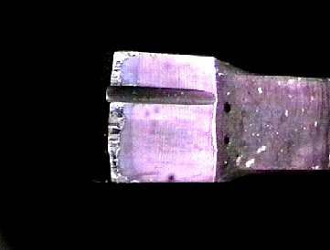
Fig.2 Wearing view of TCT edge
|
|
(2) Test results:
- The wearing situation TCT edge can be seen in Fig.2.
We confirmed the total blade life of 2m2/pc.
- The worn out amount was 0.4mm at flank and 0.5mm at
side of TCT edge which can be re-sharpened.
- The roughness on cut surface was about Ra5Ám
which was going to be decreased after cutting number
being increased.
- The burr height was below 0.15mm at both outer- and
inner-sides, and so no particular burr removing device
will be required for the most of tube applications.
- The step-gap generated by 2 different blades was below
0.1 mm and would be constant figure, if no significant
worn out at TCT edge.
- Less noise compared with Friction saw.
2.3.2 Stainless steel tube:
(1) Test method:
The tube AISI304 Ï139.8*t6.6 was applied for the testing material. TCT blade with outer
diameter Ï355mm, inner diameter Ï45mm, thickness of tip 3.1mm, number of tooth 90 (coated
by TiAlN) was applied. The cutting conditions were peripheral speed 200m/min, cut-in speed
225mm/sec, under dry cut (without any coolant).
(2) Test results:
AISI304 is one of difficult materials to be cut which has the characteristics of low thermal
conductivity, easy to be work-hardened and high affinity with tooling material. Therefore,
it has the problems of large cutting resistance, easiness of tools being worn-out due to
high cutoff temperature and the chip being easy to be sized what cause the chipping and
breakage of TCT.
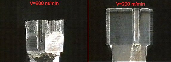
| |
Fig.3 Comparison of wear views of TCT edge
|
|
On our test machine we carried out the test (Fig. 3)
under a peripheral speed range which could be
realized as the flying cutoff machine in
accordance with our knowledge and the Taylor's
tooling life equation, and as the results we could
confirm the longer blade life than the other
existed TCT cutoff machine by over 3 times.
- In Fig.3 the comparison of the wearing limit
of tip on existed TCT and the tested one on
our machine. The life of tip on the existed
cutoff machine is 0.15m2/pc in average and the worn out amount at flank is about 1mm width
which is almost reaching its limit.
However, the cut area on the test machine was only 0.50m2/pc and is still not reaching its
limit.
- The worn out amount of tip on test machine is 0.2mm at flank and 0.4mm at side, and the
further cutoff can be continued.
- The roughness on cut surface was about Ra5Ám which was going to be decreased after the
cutting number being increased.
- The burr height was below 0.15mm at both outer- and inner-sides, and so no particular burr
removing device will be required for the most of tube applications.
- The step gap generated by 2 different blades was below 0.1 mm and would be constant figure,
if no significant worn out at TCT edge.
- Less noise compared with Friction saw.
3.4 Simulation technology for stress on TCT blade:
Recently the numerical analysis technology
has been developed and the stress distribution (Fig. 4)
on tip under cutoff works and the deformation
behavior on tip can be foreseen. Utilizing this
technology, an appropriate TCT can be designed
without any trial manufacturing and proof test
of TCT which will make possible the shortening
of developing time and saving the experimental
cost. Fig.4 shows an example of simulation of
"Maximal stress" and "Maximal deformation in
the cutting direction" which have been utilized
for selection of TCT on our test machine.
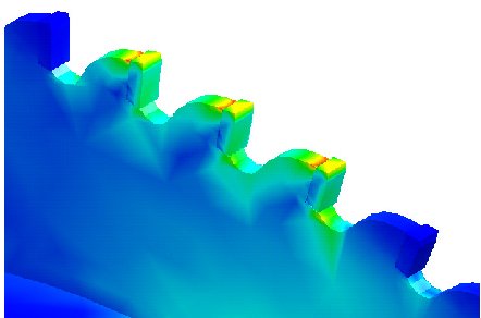

| |
Fig.4a FEM analysis of TCT deformation
|
|
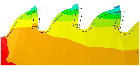
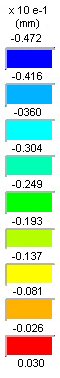
| |
Fig.4b FEM analysis of TCT deformation
|
|
However, as the life of TCT blade is depending on the mother plate of TCT, the material and
shape of carbide tip and the cutting conditions, it is necessary to decide the blade change over
timing after grasping the reference figures on actual line or tested figures.
4. Reference and Evaluation:
As you can find in Table 3 showing the reference
list of this system RFS (Rotary Fine-cut Saw),
the machines delivered not only for carbon steel
tube but also for stainless steel tube are well
operating under good performance originally
expected.
|
Model
|
Start up
|
Material
|
OD range
|
|
RFS220
|
1999
|
Carbon steel
|
Ï89 - Ï219
|
|
RFS320
|
1999
|
Carbon steel
|
Ï127 - Ï325
|
|
RFS220
|
1998
|
Carbon steel
|
Ï114 - Ï216
|
|
RFS220
|
1998
|
Stainless
|
Ï140 - Ï220
|
|
RFS120
|
1998
|
Stainless
|
Ï60 - Ï114
|
|
RFS120
|
1997
|
Stainless
|
Ï60 - Ï114
|
|
RFS170
|
1996
|
Stainless
|
Ï50 - Ï130
|
Both of tubes with thinner and heavy
gauges have no deformation and burr and are
commercialized without any large scale of after-
processing equipment like a surfacing machine.
On the machine which has been delivered to an USA
customer as results of our various tests on our test
machine, we have been reported that it is operated
under the marvelous blade life of 5~6m2/pc.
5. Future target:
In order to spread TCT flying cutoff machine further, needless to say, it is necessary to reduce
the investment cost, TCT blade cost and TCT blade re-sharpening cost. On the other hand, in
TCT cutoff for the round bar and billet the speed up with Sz (cutting amount per piece of
blade) = 0.23mm and cutting capacity = 1500mm2/sec has already been achieved.
5.1 Further speed-up:
The maximum number of cut available on the existed TCT flying cutoff machine with multiple
saw blades is up to 12 cuts/min, but we are challenging to achieve 15~20 cuts/min with which
we would like to contribute to the improvement of productivity in ERW tube industry.
Also, in replacement for the press type cutoff machine, the development of a TCT flying cutoff
machine with single blade with high speed of 30 cuts/min would be expected.
5.2 Improvement of TCT blade:
Though it will be still far away from the critical cutting speed in the theory of "Valley of Death"
written by Mr. C. Salomon, owing to the improvement of TCT in anti-wearing characteristic
against high temperature the increase in demand of ultra high speed light cut type cutoff
machine is foreseen.
There will be a possibility of ceramic tip being applied in the future, but the major use would be
a tip made of "Cermet" (a kind of ceramic and metal mixture). On the other hand, in order to be
proof against the severe conditions it will be requested that not only the improvement of tip
but also the integrated improvement of material of mother plate, heat treatment technology,
strain removing technology (so called "hammering"), brazing technology, coating technology and
the search of most appropriate cutting condition, etc.
Nakata Mfg. Co. Ltd.
- Addr: 2-12-2 Mikuni-honmachi, Yodogawa-ku, Osaka 532-0005, Japan
- Contact: Norio Mitsuhata
- Phone: +81-6-6394-1131
- Fax: +81-6-6396-7295
- www. http://www.nakata-mfg.co.jp/
- Email.
|