Ultrasonic testing of tubes and bars by computer based instrumentation
by
John Venczel
Magnetic Analysis Corporation
1. ABSTRACT
Ultrasonic inspection instruments, which are designed for production testing, are mainly computer-based today. Although the physical process and the basic principles of ultrasonic testing are the same, the presence of a modern industrial computer in the system gives it a new dimension. First, the setup parameters are remote-controlled and held in on-board registers. This makes it possible to save and recall entire setups, consisting of a large number of individual parameters. These setups can be identified by appropriate names and recalled by a simple keystroke. Second, the test results can be analyzed, processed and stored. Output devices, such as alarm horns, paint markers and sorting devices can be programmed for each type of product. As a result of the above, changeover time from one product to another can be minimized. Furthermore, the computer can generate a summary report after each production run by a simple keyboard command. This paper analyzes the capabilities of a modern computer controlled test instrument based on an existing product of the kind.
2. KEYWORDS
Nondestructive testing, ultrasonic testing, tube and bar testing.
3. INTRODUCTION
Quality control is very important in tube and bar production. First, the production machinery must be well maintained to ensure a flawless operation, but internal defects may occur under all circumstances. Nondestructive testing is the way of identifying defects in finished products. With regards to methods, both eddy current and ultrasonic testing are widely used for tube and bar testing. Eddy current testing is limited to the outside surface of the material to a limited depth, depending the frequency of the test signal and the material under test. Ultrasonic evaluation can detect flaws on both internal and external surfaces, as well as inclusions and other internal defects. In the following we shall examine the ultrasonic testing methods based on computer based test instrumentation.
4. REVIEW OF ULTRASONIC TESTING
Ultrasonic testing is the best method of nondestructive testing for tubes and bars. It can identify defects on inside or outside surfaces as well as in the full volume of the part. There are two methods of ultrasonic testing: pulse-echo and through transmission. In case of pulse-echo testing the same transducer is used as both transmitter and receiver and the testing is done from one side of the material.
Through transmission testing requires two transducers, one is the transmitter the other is the receiver and the part under test must be located between them. For tube and bar testing we use the pulse-echo method. Since high frequency ultrasound does not propagate well in gas, liquid or solid coupling medium is required, which is usually water. Production testing has to be done at high speed with minimum operator assistance. In order to achieve a full volume testing the tube has to be rotated in front of the transducer while moving forward. Since it is difficult to rotate long tubes at high speed, rotary testers were developed, where one or more transducers are rotated around the tube, while the tube moves through the rotary tester. The rotational speed is between 1,800 and 4,000 RPM and the testing speed is up to 400 feet /minute (122 m/min).
Before testing a batch of tubes the testing station has to be set up for the given product. This is done by using a calibration standard. The calibration standard is made of the same material as the tube under test with artificial flaws machined into it in form of longitudinal and transverse notches on the outside and inside surfaces to model surface braking cracks. Internal discontinuities are modeled with radially drilled flat-bottom holes or side-drilled holes, orient parallel to the axis. The calibration consists of adjusting the position and orientation of transducers, setting the gain, the position of detection gates, alarm thresholds and other operating parameters of the electronic instrumentation and activating the required outputs such as horn, sorting and marking. Testing procedures usually require running the calibration standard through the tester before and after a batch of tubes is tested. Each time all artificial defects have to be properly registered or the test has to be repeated.
5. OPERATION OF A COMPUTER BASED ULTRASONIC TESTER
Before computers and microprocessors became part of ultrasonic test instruments the set up parameters were adjusted by dials and switches located on the front panel of the instrument. Saving of an entire set up for later recall was not possible. To remember a set up one had to write down the position of each dial and switch. This was time consuming and, also, prone to error. In a computer based instrument the operating parameters are adjusted remotely by keyboard or infrared remote control. Since the operating parameters are held in the computer memory it is easy to save them for future use. Set ups can be printed for a hard copy or saved on a floppy disk. Figure 1 shows an example of a printout for a five-channel system.
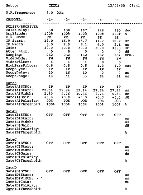
| |
Figure 1. An example of a printout for a five-channel system.
|
|
Production testing of tubes is based on a method called A-scan. The ultrasonic echoes are displayed on an oscilloscope as a function of time. In a computer-based instrument the A-scan is part of the main display on the computer monitor. There is also a strip-chart recording, which shows the echo amplitude within the flaw gate as a function of time. Strip-chart recording is an additional feature in a computer-based test instrument. In the past calibration results were recorded on strip-chart paper and a lot of paper was wasted during a calibration. In a computer-based instrument a short segment of strip-chart is displayed on the monitor to assist the operator during setup. After calibration the entire screen can be printed out for a permanent record. The strip-chart recording can be stored on the hard drive of the computer. The length of recording depends on the capacity of hard drive and it can be as long as several days or even weeks. The recording can be kept for a permanent record on floppy disk or CD ROM. Portion of it can be electronically transmitted if required. The screen-print of a computer display is shown on Figure 2.
|