Laser Profilometry as a Inspection Method for Reformer Catalyst Tubes
by Richard D. Roberts
Steam reformers are an integral part of ammonia, methanol, hydrogen, and gas process plants around the world. They are one of the highest cost, both in capital and maintenance, pieces of equipment in the plant. Typically, reformers contain several hundred vertically orientated straight tubes, referred to as catalyst tubes These tubes represent a significant cost for replacement and can be a major source of plant unavailability if unplanned failures occur. The plant operator is faced with balancing production needs against tube life and risk of tube failure. The Inner Diameter (ID) of these reformer tubes is generally between 76 mm (3.0 inches) and 127 mm (5.0 inches). During plant operation the catalyst filled tubes are externally heated to allow the reforming reaction to occur. One of the major concerns in plant operation is that the reformer tubes operate at an elevated temperature such that they are susceptible to a failure mechanism referred to as "creep". This condition exists due to the elevated temperatures and stresses imposed by internal pressure, thermal gradients, and mechanical loading cycles. Being able to identify and locate such damage in its early stages is essential for optimizing plant operation.
Conventional NonDestructive Examination(NDE) inspection techniques currently applied to reformer tubes are geared to finding creep damage in the form of internal cracking. However, with the trend towards larger tube diameters and longer intervals between turnarounds, the detection of such defects may not allow for sufficient time for forward planning of tube replacements. Also, such 'end of life' techniques do not allow any differentiation between the 'good' tubes. Early detection of underutilized tube life can prevent the lost opportunity on both unrealized production through running them too cool and tube life 'giveaway' if good tubes are discarded prematurely.
Typically, destructive testing is used on a small number of tubes removed from the reformer to try and determine the absolute life remaining. Whatever the method that is used to do this the results are from a sample size that is statistically not valid. It is imperative therefore that all the tubes are surveyed with a NDE technique to characterize their relative condition in order to make sense of the absolute condition assessment provided by the destructive testing.
Reformer tubes undergo creep strain, in the form of diametrical growth, from the first day that they are fired. The ability to accurately measure and record this growth means that the tubes' condition can be monitored from day one. Therefore, not only can individual tubes be retired from service at an appropriate time, but also the reformer as a whole can be assessed for performance. The use of the internal laser mapping technique is not only useful in preventing tube failures but has huge potential in optimizing production from the whole tube set without sacrificing reliability. Of course, external diameter measurements can be used but they are limited as the automated devices only measure across one diameter and are often access restricted by tube bowing. Manual measurements are too time consuming to provide more than a few readings per tube. Furthermore, neither way can provide diametral growth data at or through the reformer refractory. External measurements are inherently less precise as they are based on a cast surface rather than the internal machined surface and do not take into account the effects of oxide shedding. The most accurate growth measurements are obtained when 'as new' baseline data has been taken prior to the tube being fired for the first time. However, if this is not available by using the top portion of the tube that is operating outside the creep temperature as a reference diameter, the growth profile of the tube can be determined at any stage in its life. The use of laser mapping techniques on new tubes has the added advantage of providing a quality check on the internal machining.
Recently, the use of the laser mapping method referred to as "laser profilometry" has gained worldwide acceptance as a viable inspection method for the early detection and characterization of creep. Process plants in New Zealand, South America, Canada, and the United States have successfully used the laser profilometry method. Whenever reformer tubes are operating under pressure in their creep temperature range, their ID will increase over time.. Use of laser profilometry allows mapping and quantification of a tube's ID as several hundred thousand diameter readings can be acquired down its length. Since small diameter increases on the tube's interior (i.e.1% are indications of early stages of creep, it is essential to gather data with such accuracy). This is a quick process, requiring little or no preparation to the tube's interior surface, since steam reformer tubes are inherently clean.
LASER PROFILOMETRY
Over the last 15 years the use of "Laser Profilometry" has gained worldwide recognition as a viable NonDestructive Examination (NDE) method. As a result of miniature optics, higher speed signal processing electronics, and computer graphic data presentation software, systems have been developed for a broad spectrum of laser-based profilometry NDE applications. Laser profilometry utilizes a principle referred to as optical triangulation. Optical triangulation employs the use of a light source (in most cases a diode laser), imaging optics, and a photodetector. As shown in Figure 1, a diode laser is used to generate a collimated beam of light that is then projected onto a target surface.
| |
Figure 1. Laser Triangulation
|
|
A lens images the spot of reflected laser light onto a photodetector, which generates a signal that is proportional to the spot's position on the detector. As the target surface height changes, the image spot shifts due to the parallax. To generate a three-dimensional image of the part surface, the sensor scans in two dimensions generating a helical set of radius data that represents the inside surface topography of the tube. Software then generates a user friendly color graphical image of the inside surface of the tube.
A laser profilometry inspection system has the ability to acquire substantial quantities of inspection data in a very short period of time. For example, with a automated laser profilometry system, a catalyst tube 15 meters (50 ft.) in length can be inspected in approximately three minutes while acquiring well over 1,000,000 radius readings. Of course, large data files of this sort must be manageable and easy to analyze for any substantial benefits to be gained from them. Software has been designed which automatically compresses and arranges the data for easy viewing and quick analysis processing making the initial large data files a non-issue.
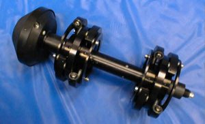
Over the last few years QUEST Integrated, Inc., and a large worldwide methanol producing company have formed a partnership resulting in the development of several custom laser-mapping inspection probes. Figure 2 is an example of a 5.0" laser mapping probe. These
| |
Figure 2. 5 Inch Probe
|
|
custom laser-mapping probes were designed to inspect catalyst tubes prior to being placed into service or during a catalyst change out. Access to the interior of the tube is essential since the laser-mapping probe must pass through the tube to gather the ID information. Probes have been designed to inspect of catalyst tubes with inner dimensions between 76 mm (3.0 inches) and
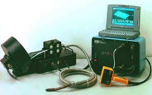
134 mm (5.3 inches). These laser-mapping probes were designed to be compatible with QUEST's Laser-Optic Tube Inspection System (LOTIS™), Model 400N (see Figure 3 for example of a LOTIS-400N system). The existing LOTIS-400N software was already capable of
| |
Figure 3. Laser-Optic Tube Inspection System
|
|
handling enormous quantities of data produced by the laser mapping probes and assembling into small manageable data files. The LOTIS software then arranges the collected inspection data into several user-friendly color graphical presentation formats. The inspection is initiated by inserting the laser-mapping probe into the upper section of the catalyst tube. An automated probe pusher inserts the laser-mapping probe downward in the vertically orientated catalyst tube until it reaches the bottom. Once at the bottom of the catalyst tube, the probe pusher automatically extracts the laser-mapping probe with speeds up to 76 mm (3.0 inches) per second. While the laser-mapping probe is being mechanically extracted through the catalyst tube, the probe's laser head spins at 1800 rpm. Up to 360 laser data samples are being gathered for each revolution of the laser head. In approximately three minutes, the probe reaches the top of a 15 meter (50 ft.) long catalyst tube. The inspection technicians then move on to the next tube to be inspected. After the data collection process is completed, the inspection data is readily available to be analyzed.
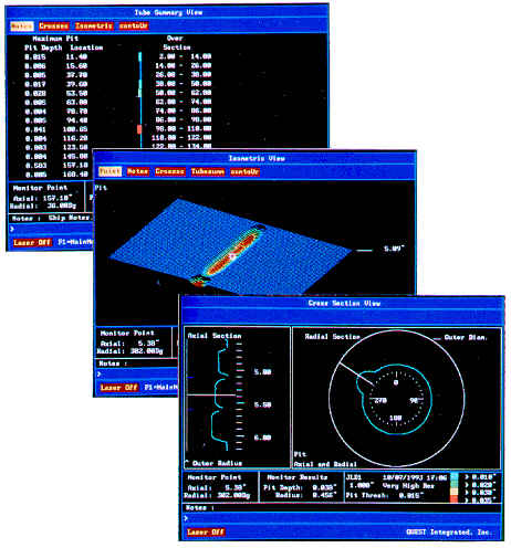
The entire catalyst tube's interior surface is viewable in a straight-forward format which allows damages to be located and easily quantified on or off-site. Three different views (contour, 3D isometric, and cross sectional) can be viewed to allow for easy and accurate interpretation of flaws or growth (see Figure 4). The analysis can be performed in the field to allow for on the spot decisions as to repair or replace options.
| |
Figure 4. Three LOTIS Views (Contour, 3D Isometric, and Cross Sectional)
|
|
In addition to the color graphical presentations, the LOTIS software generates a separate file providing diameter readings in axial increments as tight as 0.254 mm (0.010 inch) or ten diameter readings per inch. The diameter output file is in ASCII format to allow 3D modeling of the reformer tubes (see Figure 5). Whereas the individual tube results are used for 'per tube' decision making this 3D visualization gives the overview of the cumulative creep damage in the reformer. This can be used to adjust the thermal profile in the reformer to optimize tube life and production.
| |
Figure 5. Diameter readings in axial increments
|
|
PERFORMANCE
QUEST and its partner first utilized the LOTIS technology at a methanol processing plant. The plant had experienced a high temperature corrosion mechanism referred to as "metal dusting" (see Figure 6 for example of metal dusting) the outlet pigtail in the lower 635 mm (24 inches) of the reformer tubes. Metal dusting is a condition where the process stream attacks the interior of the reformer tube with subsequent, significant metal loss. This can be severe enough to be the life limiting condition for the tube. Typically, the metal dusting damage is isolated to a 360° circumferential band around the catalyst tube's interior surface where the critical temperature range exists. External access was difficult and external ultrasonic examination hampered by the as cast surface. Internal visual or depth measurement was difficult at that depth down a narrow tube. This particular reformer design has flanges at the lower section of each individual tube which allowed the laser mapping probe access from the bottom. The laser-mapping probe was inserted vertically a total of 914 mm (36 inches). The interior surface of the reformer tube was
| |
Figure 6a. Metal Dusting
|
|
| |
Figure 6b. Metal Dusting
|
|
mapped while the laser-mapping probe was being extracted. Immediately upon completion of each scan the amount of damage could be quickly assessed on a portable laptop computer. This provided the plant engineers with precise information allowing them to immediately make decisions with regards to repair requirements. In addition to quantifying the metal dusting damage, inner diameter readings were acquired every 1.3 mm (0.050 inch) down the tube. This information could then be used to compare the hot portion of the tube against the cooler part to determine if inner diameter growth was occurring above the pigtail.
On another occasion, QUEST applied the LOTIS technology in a reformer furnace at a fertilizer plant. These particular tubes were orientated horizontally, which required use of an air mover to transport the LOTIS probe to the far end of the tube. Several 15 meter (50 foot) long tubes were inspected for the detection of fluid level corrosion. In this particular case, the damage was isolated to the gas and air interface line region of the tube. The damage ran down the full axial length of the tube, which provided an ideal application for laser profilometry (see Figure 7).
Immediately upon completion of the data collection the results clearly quantified the damage depth and provided precise axial positioning. Based upon that information, the fertilizer plant engineers were able to make necessary modifications to the unit design and operating parameters.
| |
Figure 7. Axial Grooving Damage in Reformer Furnace Tube apparatus
|
|
CONCLUSION
Laser profilometry is an exciting and new inspection method for steam reformer tubes worldwide. Its speed, precision, and accuracy allow for early and mid life creep monitoring previously unobtainable. QUEST will continue researching new applications of laser profilometry within reformer piping systems.
For additional information with regards to applications of laser profilometry, please contact QUEST Integrated, Inc., at (253) 872-1358 or visit our web site at http://www.qi2.com.
For further information or a demo-version please contact:
QUEST Integrated, Inc.
- Addr: 21414 - 69th Ave. S. Kent, Washington 98032 USA
- Tel: 1-800 233-3345 ext. 275 Direct 1-253 872-1275
- Fax: 1-253-872-8967
- WWW: http://www.qi2.com/field/fsddef.htm
- Email.
- Contact: Richard D. Roberts
|