
| THE SITE FOR THE TUBE AND PIPE INDUSTRIES |
|
Joining coils together is becoming more and more popular in the press industry. By eliminating rethreading, you will greatly reduce scrap, tooling damage, downtime and safety hazards. Coil end welding is currently very popular in the roll form and tube mill industries. In fact, nearly all Tube Mills utilize coil end welders. One of the biggest justifications for utilizing coil end welders is the reduction of time spent during the coil change. That is, it is generally faster to weld coils together than to rethread a processing line. In the Tube and Roll Form Industries the higher speeds use more coils per shift making the coil welding process more easily justified through the reduction of coil related downtime. In the press industry, on the other hand, the reduction in scrap, tooling damage, and reduced safety hazards, also play a big factor in the justification of coil end welding. On most progressive dies, the operator will throw away 5 to 15 feet of material at the end of each coil. By welding coils together scrap can be reduced by as much as 90%. The savings can be thousands of dollars for 1 shift and much more for 2 or 3 shifts. This savings can be multiplied several times for non-ferrous materials. The chart below shows a typical downtime cost study based on profit per foot. By welding coils together you can cut coil change downtime by as much as 90%. It usually takes 5 minutes to as long as 30 minutes to rethread some of the larger progressive dies. Below is a basic chart showing some payback on a typical press. Additional downtime justification papers are available and go into detail with formulas on how to justify coil joiners.
Tooling damage and safety hazards are hard to measure. However, the majority of tooling damage comes from the lead end of a new coil being threaded into the die. Although you cannot determine how much tooling damage will be eliminated by the addition of a coil end welder, many progressive die manufacturers have justified coil end welders on this issue alone. Therefore, it should be considered very seriously. You should also consider the downtime related to changing damaged dies. This can be eliminated if the die damage did not occur in the first place. In addition, the fact that the operators no longer have to manually feed the press will result in a safer work environment.
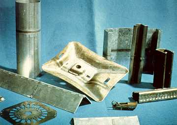 Figure1. Typical parts with welds in them after forming.
All of the advantages above are making the press industry turn toward coil end welding. Although there are many methods of joining coils, the TIG weld process has proven to be the best and most economical for the press industry. Thirty years ago, very few press companies would consider the idea of running a weld through their dies. However, with the advances in coil welding equipment and the TIG weld process, the press industry has become a significant amount of the total coil end welder market in the U.S. Proper shearing and aligning of the two coil ends allows for an automatic TIG torch to lay a weld bead that will easily pass through the progressive die tooling. The TIG weld is approximately the same thickness as the parent metal because no filler wire is added. An electric arc is passed from a non-consumable electrode to the parent metal resulting in a fusion weld. The weld is very smooth and approximately the same hardness as the parent metal. The automatically driven weld torch allows for a smooth and consistent weld bead across the seam of the material. Coil end welders come in semi-automatic portable versions and fully automatic stationary versions. The portable units can be used on more than one line and are generally for 15" wide material and less. The stationary units are for heavier gauges such as strip thickness over .125" and coil widths up to 84" wide or more. (Figure 111 shows some typical parts with welds in them after forming.)
Portable welders usually require manual positioning of the strip into the shear and weld station. The welder is pulled into line on a track or on the floor when the tail end of the coil drops off the uncoiler. To assure a square cut, the tail end strip is pushed up against edge square edged guides. The tail end is then cropped by a precision shear to get a very clean burr-free edge for welding. The shear can be manual or air for light gauge strip and is usually hydraulic for heavier gauge. The powered shears will usually have spring loaded pressure pads to hold the strip during shearing to prevent any movement, assuring a square cut. After the tail end is sheared, it is moved to the weld clamp station. The clamp station is directly above the shear for a handless machine or it can be on the same passline side by side for easier positioning on heavier gauges. The strip is then pushed against edge guides and a gauge to be sure the back edge is aligned and the sheared edge is on the centerline of the torch. At this point the operator pushes the weld start button and the weld torch establishes an arc and travels across the seam welding the two strips together. Figure 222 shows a typical portable coil end welder. 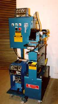 Figure 2. Typical portable welder.
On heavier gauge strips, stationary welders are usually used. Stationary machines come in many different designs from semi-automatic to fully automatic. Both single cut shears and double cut designs are available for faster overall cycle time. With all stationary designs, the strips are sheared and positioned for welding by the machine. This allows for very wide and heavy strips to be properly sheared and positioned for welding without the operator having to handle the material. The strip runs through the welder at all times so the welder does not have to be pulled into line for use. The shear and weld clamps have a three-inch opening and passline rolls prevent the strip from rubbing on the machine components. The operation starts by jogging the tail end into position in the shear station. The strip is then edge guided automatically or by manual hand cranks to put it on center or a fixed back edge. The strip is then clamped and sheared. The lead end of the new coil is fed into place over the pre-sheared tail end and is edge guided, clamped and sheared. The scrap piece is removed by hand or automatically. The shear then indexes out of place and the weld station into place. The weld clamps are closed and the weld torch is initiated, joining the two coil ends together. After the weld is complete, all clamps are opened and the machine is reset for the next cycle. On double cut designs, both coil ends are cut in a four-inch opening and the scrap automatically drops out the bottom of the welder. The coil ends are then indexed together for an overall faster cycle. However, it requires that the strip has at least 2 inches of slack at each end of the welder for indexing the strip. Figure 333 shows a typical stationary welder. 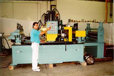 Figure 3. Typical stationary welder
Whether semi-automatic, fully automatic, stationary or portable, coil end welders are easily justified on most progressive die lines. The increase in press up time and the great reduction in tooling damage and scrap have made coil end welders very popular in the press industry today. To remain competitive in the future, it is important to use the latest in technology to keep your valuable machinery up and running at its full capacity.
For more information please contact: |