| THE SITE FOR TUBE AND PIPE INDUSTRIES http://www.tubenet.org |
Hartmut Kümmel, INSTITUT DR. FÖRSTER, Germany
 ABOUT THE AUTHOR: Hartmunt Kümmel, Export General Sales Manager, has been with Institut Dr. Förster for over 30 years, having begun in the development and service department. He has specialized throughout his Förster career in the field of Eddy Current and Magnetic flux leakage technology.
Tubes made of nonferrous metals are manufactured for an extremely wide variety of applications and must consequently meet the applicable requirements. Proof must be furnished that the requirements are met. Some of these requirements relate to testing for leaks and freedom from surface damage on the products. These requirements can be met using nondestructive testing methods. Nondestructive testing, in particular eddy-current testing as one of these methods, has long proven its worth for in-process testing of these products. Tubes made of copper are particularly important in this respect, both as regards quantity and as regards the test requirements. Most of these products are used for piping, heat exchangers, air-conditioning and cooling. The need for testing, both as regards quantity and as regards requirements, increases as tube dimensions decrease. There are a number of standards covering nondestructive testing stipulating minimum requirements applicable to quality. These requirements can be met using the eddy-current through-type coil method. However, many users and manufacturers are now applying far more stringent test requirements. This is related to the fact that tubes with thinner and thinner walls are being used in order to reduce the quantity of material used and in order to cut costs. These more stringent requirements can be met only with eddy-current testers with rotating scanning probes. The punctiform probes of these testers provide a far higher flaw resolution, thus allowing detection of even small linear flaws of shallow depth. This application is always implemented together with through-type coils in order to detect all flaws over the entire surface reliably even at high throughput speeds. Extensive experience is available in relation to integration of the testers at a suitable point on the production lines - frequently directly in the drawing units or rewinding units. Particular attention must be paid, above all, to guidance of the material in order to achieve optimum test results and allow problem-free use. Moreover, nondestructive testing can now perform far more extensive tasks than simply checking that the end product if free of flaws. The test represents an important measure, the results of which allow statements to be made on the condition of the production lines. Consistent use allows process deficiencies to be detected at an early point, allows condition-dependent maintenance and servicing of the production facilities and thus helps both to enhance the quality of production and to cut production costs. 2. Production methods for nonferrous tubes The most popular methods involve production of the initial tubes by extrusion or cross-rolling from rod stock or casting this initial material directly using the continuous hollow casting method. The tubes are then further-processed by cold pilger rolling, planetary rolling and drawing. The final production steps for achieving the final size almost always involve drawing processes. The end product is straightened and supplied either cropped to length or coiled (LWC, Pancake in the case of copper tubes). Figure 1 shows such a typical manufacturing sequence.
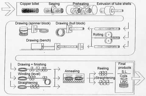 Figure 1. Manufacturing sequence Inspection measures for quality inspection and quality assurance may be integrated at all stages of production. Online processes for continuous inspection for flaws at the upstream stages prevent unsuitable material being further-processed. In most cases, in particular in the case of copper tubes, the finished product must be subjected to an inspection so that only flawless material is supplied and so as to avoid complaints.
It is largely eddy-current methods that are used for nondestructive testing for leaks and surface flaws. Basically, two methods are available:
Through-coil method:
Rotating scanning probe method: Figure 2 shows the principles of the methods described above. The physical properties and the specific details of the units based on these methods are described in greater detail in the Section entitled Testers.

 
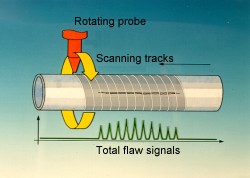 Figure 2. Rotating Scanning- and Through Coil methods
Generally conventional requirements applicable to nondestructive testing are as follows:
Eddy-current testing is able to meet all the above requirements.
Initial material (parent material) is tested in cases in which information on the quality of the product prior to further processing steps is to be obtained as early as the preceding steps of the production process. This avoids unnecessary costs as the result of further-processing unsuitable material. However, this also allows the manufacturing process itself to be monitored and controlled. Tests during this phase may be necessary in order to meet the requirements of controlled production in accordance with ISO 9000. Evaluation of the test results and analysis of the causes, as methods for enhancing the process, may contribute substantially to cutting costs. Many manufacturers have already installed initial (parent) material tests. Testing is conducted in this case on the basis of internal targets. 3.2.2 Testing the finished product Testing of the finished product is generally conventional but is mandatory in the case of tubes made of copper and copper alloys. A series of Standards relating to testing of the finished product (Figure 3), exists for such tubes in particular.
Figure 3. Test standards
The Standards listed below and published by various institutions in the individual countries are the most important Standards for tubes made of copper and copper alloy for general applications and for heat exchangers, air-conditioning equipment and pipes for sanitary applications (water and gas):
The Standards prescribe the test flaws to be used, the methods for instrument setting and, in some cases, the procedures for flaw evaluation. In general, bores through the wall are defined as reference flaws. ASTM 243-90 also foresees filed notches of defined depth. The table in Figure 4 provides an overview.
Figure 4. Test Standards
3.2.4 Application of the Standards on units with through-type coils or rotary scanning The above-specified Standards for copper tube testing are tailored to the use of through-type coils and are complied with by these instruments. The Standards currently make no distinctions between testers with through-type coils and testers with rotary scanning, apart from the fact that, in some cases, different threshold settings are permitted. To date, there are no Standards specific to rotating instruments.
Since many of the heat exchanger tubes now feature extremely thin walls (down to 0.3 mm) and since use of internally finned tubes is now also more popular, the flaw sensitivity achievable with the through-type coils is now no longer sufficient for quality-conscious manufacturers and users. Very frequently, Japanese manufacturers or those manufacturing for the Japanese market, but also European manufacturers, impose test requirements extending well beyond the requirements of the Standards and the industrial standard conventional to date. This involves detecting other types of manufacturing flaws with a very shallow depth. For example, this includes "line flaws” or "zipper defects” which are not detected with the through-type coil method. Roating instruments can perform this task adequately only because they allow a correspondingly higher sensitivity to be achieved. However, using only rotating instruments is inadequate at the throughput speeds which are very frequently high since the scanning track coverage of the surface is incomplete, thus not allowing the bores prescribed by the Standards to be reliably detected. In such cases, it is advisable to use a combination of through-type coils and rotating instruments. This combination of test methods meets the stringent requirements as imposed today by demanding manufacturers and users.
4.1. Mode of operation of the Eddy Current test method The test method is in accordance to DIN 54140 detailed described. The encircling test coil´s primary (field) winding is supplied with a alternating current and induces „Eddy Currents" in circumferential direction of the test piece. Defects displace locally the path of the Eddy Currents. Those changes of the Eddy Current cause variations of the voltage in the secondary windings of the coil when the test piece passes the coil system. Phase and amplitude of these voltage variations are evaluated and provide an indication of the size and type of defect. The complete transmitter system of this unit consists of a D. C. magnetization yoke into which the test coils matching the diameter of the test piece are inserted.
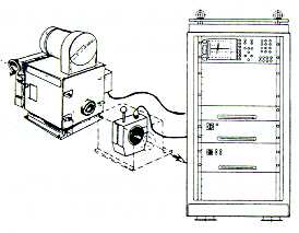
This method is the simplest test method which, as already mentioned, involves the material moving axially through a coil surrounding the material. The diameters of the coils are matched to the material under test. The diameters available range between 0.3 and 180 mm. The instruments can be used, in principle, at very high throughput speeds ranging up to 120 m/second. Ultra-modern computer systems are used to process the signals of the test system generated by the eddy-current effects. These systems feature menu-prompted operation with softkeys on the controller as the central operator-control, display and control unit. Extensive documentation of all instrument parameters and results is possible thanks to extensive storage and output facilities. All important instruments functions are monitored. The test frequencies can be selected in a broad range. Figure 5 shows instrument electronics of this type.
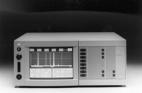 Figure 5. Testing instrument The newly developed software for copper testing allows for the special requirements of the test specifications to be applied when further-processing the signals, such as the test specifications of European Standards prEN 1971 for tubes made of "copper and copper wrought alloys”: These standards define "local discontinuities” (local defects) and "non-local discontinuities” (non-local defects). Prescribed bores are used to set the first sorting limit (threshold) for local defects. A second sorting limit (threshold) set to a far low flaw signal magnitude is used to detect non-local defects, whereby a flaw is "detected” only if an adjustable number of threshold transgressions occurs within an adjustable length section (flaw density). The flaws determined in this way are considered as a local defect. The Standard does not prescribe the setting of the second threshold or the number of threshold transgressions which must then be rated as a flaw. These parameters are defined by the user or his customer. Figure 6 recapitulates the evaluation requirements.
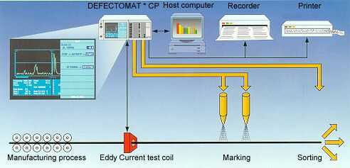 Figure 6. Defect detecting
The test instruments must comply with the prescribed test requirements with absolute certainty. Moreover, the test must be documented. Nowadays, these are the determining factors in the sector of quality inspection and quality assurance since producer liability for products is increasing continually in importance. For this reason, the electronic systems of the testers incorporate extensive documentation options. Certain forms of evaluation and representation have been introduced for applications in the field of copper tube testing. Such screen displays of the results are continuous display of the analogue amplitudes over the workpiece length and result listings for coils or workpieces. Figure 8 shows an evaluation report. To date, the Standards do not prescribe any aspects of logging but prEN 1971 implies that inspection documents will be stipulated in future by the Standards Commission.
The scanning principle with rotating eddy-current scanning probes is suitable for detection of flaws with a depth of approx. 30 µm and deeper, regardless of how these flaws are distributed over the length. The probes rotate at high speed about the material under test which is moved longitudinally and scan its surface helically. Each of the punctiform-action scanning probes scans only a small area of the material's surface at any one moment. This concentration on a very small part of the overall circumferential area means that even a minute material flaw represents a major disturbance. The rotating probes thus reliably indicate ultra-small material flaws with maximum resolution. One crucial advantage of the rotary scanning method over the through-type coil relates to flaw detection of long-drawn-out flaws. Whilst the through-type coil generates a signal only at the leading and trailing edges owing to its differential action in test direction, the rotating probe passes over the flaw with each revolution and emits a signal each time. Long-drawn-out flaws are thus indicated over their entire length and at the correct depth. For physical reasons, a high flaw sensitivity can be achieved better the smaller the rotating probe used is and the smaller the air gap between probe and material surface. Influences of the air gap which cannot be maintained precisely constant can be compensated for within certain limits electronically with an automatic compensation circuit in order to maintain a constant test sensitivity. Owing to the requirements and the technically sophisticated demands, rotating test systems are the most highly developed eddy-current test instruments available. For technical reasons relating to the process, the test heads with the rotating probes incorporated in these testers have a very small clearance of only a few tenths of a millimeter to approx. 2 mm from the test piece surface with differently set material diameters and, at the same time, central location of the test piece. This requires very precise preconditions for diameter setting in order to achieve reproducible test settings. Arrays with axially moveable test heads (quiver system) or rotary-mounted test head levers have proven successful in practice. On the version with axially moveable test heads, the diameter presettings are generally made by turning a spiral or cam disc. One disadvantage of this system is the fact that it is absolutely essential to protect the test head against damage. A pivoted lever represents a relatively low-cost test head array which can deflect when it contacts the test head in order to avoid such damage. High-performance rotating instruments in four diameter ranges (Ro 14, Ro 30, Ro 65, Ro 130) with testable diameters ranging from 2 to 130 mm are available as tried-and-tested units. Two to eight channels and rotating probes with 1.5 mm, 2.5 mm or 5 mm track width are used, depending on the required flaw specifications and testing performance. The rotating heads are selected on the basis of the diameter range. Depending on probe design, the rotating heads Ro 14 and Ro 30 to be used for the sector of small copper tubes to which this article is chiefly devoted permit testing without omission at speeds of 3 m/second. Since speeds of up to 8 m/second or more are used in the rewinding systems, this results in gaps between the test tracks (diagram Figure 11). Consequently, the rotating instrument is generally used together with a through-type coil instrument.
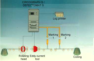
With respect to flaw detection, a combination of both test systems offers maximum performance. The short flaws not detected by the rotating instrument are detected by the through-pipe coils and, by contrast, the rotating instrument detects the long-drawn-out flaws of shallow depth detected only inadequately by the through-type coil. Although two separate evaluation units (CIRCOGRAPH and DEFECTOMAT) were required with previous, old instrument technology, it is now possible to implement a combination of CIRCOGRAPH S and incorporated DEFECTOMAT channel in a particularly compact design (Figure 7) thanks to the current generation of FÖRSTER system instruments owing to the modular functional structure. Central operator control and display, control, evaluation and logging of the test sequence of both test systems with one single controller provides a low-cost arrangement for the user with advantages in use.
DEFECTOMAT S-channel
5.1 Integration of through-type coil instruments In the majority of cases, testers with through-type coils are installed in rewinding systems. Figure 8 shows the basic arrangement. However, a whole number of instruments are also integrated in drawing systems. One of the leading manufacturers of tube drawing and rewinding systems is Messrs. Schumag whose lines are equipped with the DEFECTOMAT or CIRCOGRAPH testers within the framework of our more in-depth cooperation.
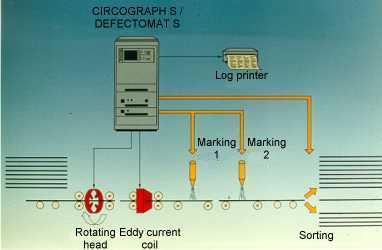 Figure 8a. SCR Line (Straightening cutting recoiling to pan-cakes).
Very suitable guides have been designed using polished carbide-metal guide inserts, as also mentioned in conjunction with the test instruments with rotary scanning. Customers are also very satisfied with such guides since they reduce the incidence of abraded copper deposits on them as well.
The characteristics and, in particular, the advantages of test instruments with rotary scanning have been explained in the preceding chapter. The clearances between probe and surface are only very small in order to achieve high test sensitivities. For this reason, guidance in this case must be particularly precise. A special guide device has been developed for testing the copper tubes, in particular the thin-walled copper tubes. This involves guides, each with two guide inserts with diameters which are slightly larger than those of the tubes under test on both sides of the instrument. This guides the material almost ideally centrally and free of vibration through the test instrument. In addition, the test heads are very well-protected against destruction as the result of deformed tube leading and trailing edges. Excellent experience has now been made with guides of this type in many applications, both with test head size Ro 14 and with test head size Ro 30. Figure 9 shows an example of an installation as is typical for a rewinding line. One through-type coil transmitter system and a rotating instrument Ro 30 are included. Since setting the correct height of the material with the straightening rolls is considered to be too difficult for the operating personnel, a lifting/sliding table has been included. This table is common to both instruments. 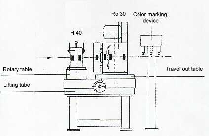 Figure 9. Typical installation of rewinding line
We are only able to demonstrate but a few typical examples of test results at this point, from the large number of applications to date for the widely ranging types of nonferrous tubes - including tubes which are smooth on inside and out, internally finned tubes or, in special cases, also externally finned tubes: Figure 10 shows the signals of copper tubes with 3 bores offset on the circumference when conducting DEFECTOMAT testing with through-type coils. The signals of the bores prescribed by the Standards are very distinct against the background noise.
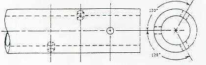  Figure 10. Signals of artifical defects by DEFECTOMAT (3 bore hole dia. 0.8 mm, each displaced circumferentially) Figure 11 shows test results of copper tubes with 9.52 mm diameter and 0.4 mm wall thickness, as obtained from very small, long-drawn-out flaws when testing with the CIRCOGRAPH rotating tester (upper illustration). They indicate the excellent flaw sensitivity offered by this unit for this type of flaw. By contrast, the lower illustration shows the results of the DEFECTOMAT on which the signals of this type of flaw achieve only far lower amplitudes and would not yet exceed the threshold at the normal instrument setting which avoids pseudo shares.
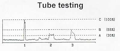 Figure 11. EC-Test by CIRCOGRAPH S
Objective test results and corroborated documentation are determining factors in the sector of quality inspection and quality assurance owing to the liability of producers for their product. However, nondestructive eddy-current testing can do far more than simply sort the finished products into GO and NOGO parts. One important aspect nowadays is integration of testing in the manufacturing process. The resultant advantages are the capabilities of monitoring the process, avoiding downtimes and cutting maintenance and servicing costs. In conjunction with ISO 9000 or also independently of it, the test results can be used to draw conclusions as regards the quality of the process from flaw frequency trends. Manufacturing defects can be avoided by recognizing the problems in good time and taking appropriate measures. This method of drawing conclusions as regards the process and deriving measures to optimize the process from these conclusions is already being used successfully by certain customers (as they have confirmed to us, without, however, informing us of details of the action taken). The flaw frequency can also be used as an indicator for the need to carry out servicing and maintenance. It allows condition-related maintenance and servicing intervals to be introduced. This allows costs to be cut by comparison with fixed servicing and maintenance intervals. This is already being used successfully at another point - when drawing steel wire - in order to automatically detect wear on drawing dies from the change in noise level and, from this, to derive information on when maintenance and servicing need to be carried out, dependent on conditions. In future, multifunctional use of the testers for the above tasks will represent one of the most important tasks for nondestructive testing. On no account should the capabilities which it offers be ignored since they do, ultimately, allow production costs to be cut. Use of nondestructive testing pays off. It can save a great deal more than it costs.
A detailed description of nondestructive testing of other products made of nonferrous materials at this point would go beyond the scope of this report. However, we shall briefly mention testing of copper rods and copper wire where testing with through-type coil instruments has been introduced to the greatest extent. Many testers are also used for sections, strips and sheets. The number of units used for steel tubes and steel wire - both through-type coil instruments and rotating instruments - runs into the thousands.
Further-processing plants virtually always produce complex, high-quality products and installations for chemical processes, supply, cooling and heating from nonferrous tubes. The material is highly deformed during processing. The requirements applicable to it are exceedingly high accordingly. Flaws and failures detected only in the end product mean high losses. Flaws which occur only during the application phase may lead to enormous claims for compensation in damages. No further-processing plant will thus use untested material. What is needed is flaw testing with a high detection sensitivity! The aim is:
For testing of copper tubes considered in somewhat greater detail in this report, the Standards stipulated by various institutions represent only the minimum requirements. Nowadays, quality tubes must comply with far more stringent specifications. For instance, in order to improve heat transfer on heat exchangers, the wall thicknesses have been made thinner and thinner. Values of 0.3 mm are now already conventional. Test specifications of a Japanese manufacturer extending well beyond the Standards have been quoted as an example of requirements currently conventional. Such high test sensitivities for surface flaws now required by many users cannot be met with the conventional through-type coil method alone. The use of instruments with rotating scanning probes is essential for meeting these requirements.
Nowadays, test instruments are becoming more and more important as a means of monitoring the manufacturing processes and as elements of a controlled manufacturing process to ISO 9000. In such cases, use of instruments may be necessary not only in final inspection but also in upstream production stages. Consequently, other important aspects are as follows:
Extended evaluation of the test results allows conclusions to be drawn as regards the process sequence or any necessary maintenance or servicing from trends in flaw frequency. This permits manufacturing flaws to be avoided by prompt maintenance and servicing resp. the introduction of condition-related maintenance and servicing intervals and resultant cost savings. The objectives specified above - quality assurance, reduction in complaints and rights of recourse owing to flaws and avoidance of unnecessary costs - are achieved by extensive use of nondestructive testing. Nowadays, using test instruments may no longer be considered as a cost factor. Rather, it can save far more than it costs! The FÖRSTER company has been constructing rotating instruments for over 30 years now and test instruments with through-type coils for far longer. As a result, the experience which the company has acquired a wealth of experience in the use of test systems which meet today's requirements, i.e. cutting manufacturing costs and safeguarding competitiveness on the market.
Institut Dr. Förster
|