Improved Mill Drive System
By Keith Barraclough – Managing Director of Doltec Limited
Tube mills and Roll-forming mills have a common design feature - they rely upon gear driven rolls to form and feed the product through the process. They also have common problems - the root and the rim of profiled rolls are moving at different linear speeds and each driven roll might not be rotating at the speed required by the strip. Mill and roll designers are thus faced with a considerable challenge and have, in the past, been forced to accept a compromise.
This article describes a mill drive system which, by means of specially designed couplings inserted in the drive to the rolls, can almost completely eliminate the adverse effects of these seemingly insoluble problems. The patented drive system can be retro-fitted to most tube and roll forming mills, is easily incorporated into new mill designs and, when fitted, provides a substantial reduction in mill drive power, reduced roll and transmission wear, and a significant improvement in product quality and consistency.
Current Practice
The majority of existing tube mills are designed to operate on a fixed base line concept where the root diameter of each lower roll is essentially constant. With this design concept it is not necessary to adjust the height of the lower rolls when changing from one size of tube to another. In addition, all the lower rolls can be driven at the same rotational speed.
In this article there is a point on the profile of each roll, referred to as the drive point, which is determined by maximum frictional load and minimum speed difference between roll and strip.
In an ideal mill, the diameter of each roll at its drive point should be such that the linear speed of the roll surface at that point precisely matches the speed of the strip. Unfortunately, it is virtually impossible to achieve this condition in day to day operation because the actual drive point changes with the thickness and strength of the material, the profile of the roll, and the setting clearance between upper and lower roll.
| | Figure 1. Typical breakdown roll pass
|
|
Consider first a typical breakdown roll pass (Fig.1) with upper and lower rolls driven directly from the output of a gearbox. The rim of the lower roll has a significantly greater diameter than the root and, because of its greater circumference, is therefore running at a higher linear speed. The upper roll has a major diameter which is typically designed to match the linear speed of the upper surface of the strip coincident with the root of the lower roll. However, the linear speed of each point of contact on the upper roll is reducing as it moves towards the rim of the lower roll. The difference in surface speed between the upper and lower surface of the material as it approaches the rim of the lower roll, is now substantially greater than root to rim speed difference of a single roll.
In most mills, the upper rolls in later breakdown passes are of increased diameter in order to accommodate strip curvature, and gearbox top to bottom ratios are changed to compensate for the larger roll. The larger diameter provides a smaller speed difference between major and minor diameters of the upper roll but does not overcome the problem.
If the lower roll could freely rotate, with the drive applied only to the upper roll, the actual drive point would then be determined only by strip thickness, tensile strength, roll design, and setting clearance. Because this drive point would be coincident with the maximum pressure point and therefore minimum speed differential against the upper roll, the reaction through the material would be to provide a coincident drive point on the lower roll. Obviously, if the lower roll is driven and the upper roll allowed to rotate freely, a similar condition would apply.
Next, consider material leaving one breakdown pass and entering the next. If significant force has been applied to form the product, it is likely that will be there could be some elongation of the strip and some increase in width. The following pass, being gear driven, has not only the upper/lower drive point conflict, but also has to accept material which may be travelling slightly faster or, in some cases, slower than the roll designer has allowed for. However, some point on either upper or lower roll will undoubtedly match the strip speed exactly and, if the roll could automatically rotate at this speed, the conflict would be removed.
These conditions apply in each breakdown pass and it should be understood that the drive points are changing dynamically roll to roll and pass to pass due to changes in strip parameters.
The current fashion in tube mill design is to employ a finite element or 'cage forming' section between breakdown and fin passes. Whilst this addresses the root-to-rim and root-to-root problem in a small section of a mill, the strip still has to be driven by conventional rolls in breakdown, fin, and sizing sections. Additionally the cost of such mills is substantially higher than traditional mills and the drive point issue remains with all driven rolls.
In the subsequent fin and sizing or calibration roll passes where the product is being shaped with rolls acting only the external surface, the root-to-rim and root-to-root speed differences apply in exactly the same manner as in the breakdown passes.
Consider initially a fin pass in a tube mill where a vertical load is applied to the top roll (Fig.2).
| | Figure 2. Vertical load is applied to the top roll
|
|
This action squeezes the strip against the fin to condition the strip edges, to produce the desired tubular profile, and maintains the open seam in a particular position. The resultant distribution of force is to provide substantially equal radial loads around the whole periphery of the tube. Each finite element of radial load has a similar load alongside it - except at the rim. At this point, where there is a gap between upper and lower rolls, the load of the finite element is doubled because there is load on one side but no load on the other side. Unfortunately, this greater load occurs at the point of maximum speed difference and often leads to pick-up and marking of both roll and product. In order to minimise this condition, roll manufacturers provide a variable radius at the rim to give a gradual relief of the point load - the speed difference however is still present.
As in the breakdown section, there is a potential elongation of the product between passes due to the compression applied by the rolls. The following roll passes are presented with material that can be travelling faster and, even if some 'progression' is applied, there is no guarantee that the roll speeds match the strip speed. This can only make the rim condition more critical.
The most successful attempt to reduce the effect of the root to rim speed difference has been to utilise 'floating flange' rolls that are provided with free running rims. The design ethic is thus to provide drive solely at the root of the roll and allow the rim to rotate at a different speed and act as a 'free forming' device. This system partly addresses the root to rim speed differential but takes no account of the root to root speed difference between one roll pass and the next, or even the root to root speed difference between upper and lower rolls in the same pass. It will be obvious that the material, roll, and setting clearances will affect both linear and transverse dimensions of material passing between one roll and the next and, with gear driven rolls, there is no dynamic compensation available for these variables.
In all driven passes it is impossible to project the exact dynamic drive point on any particular roll because the variables in material and roll settings change the condition hour by hour and even minute by minute. Roll design under these conditions has to be a compromise and it is a credit to roll manufacturers and tube manufacturers that an acceptable product can be obtained in daily production.
In many ways there is a greater problem in the sizing/calibration section where there is a definite but variable elongation between passes. Changes in elongation are under the control of the mill operator who has to make suitable adjustments from time to time in order to obtain the precise profile and dimension required of the finished product.
In an effort to address the pass to pass variation in breakdown, fin, and sizing sections, an element of 'progression' is typically incorporated in the roll design. The term 'progression' refers to the small increase in the root diameter of each succeeding roll in order to try and compensate for the elongation produced as the strip 'progresses' through the forming process. It will be apparent that such changes in diameter can only apply the correct compensation if the strip is of exactly the correct thickness and tensile strength, the rolls are the correct profile and not worn, and the rolls are precisely set to the design clearances - conditions which rarely, if ever, occur!
In the absence of anything better, progression has come to be accepted as the norm. The strip is mostly under tension as it proceeds along the mill and the effect of variable drive points is essentially averaged out, some rolls driving the strip forward and some effectively applying a brake to the strip where it is trying to move faster than the roll at it's design drive point. The mill operator must continuously monitor the product and, in the event of variations in strip dimensions and properties, is required to make small adjustments at the right point in order to maintain acceptable product quality.
In each of the above conditions, it will be apparent that wherever there is conflict in drive point, either between vertically or longitudinally co-operating rolls, substantial wasted energy will be applied to the strip. This energy gives rise to marking and distortion of the material, marking and wear of the rolls, and is reflected throughout the drive system in higher loads and greater power input.
If each roll could rotate at the speed of the strip, at the point on the roll where the strip is exerting maximum pressure and minimum speed difference, the effects of the problems outlined above would be virtually eliminated. Under these conditions, there would be no negative drive. Each roll would make its contribution to driving the strip forward and forming it to the desired shape.
The Solution
The patented CyberDrive ™ mill drive system comprises mechanical couplings which are installed typically between each gearbox output shaft and universal drive shaft to replace the existing fixed coupling (Fig.3).
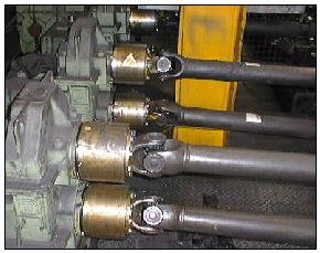
| | Figure 3. CyberDrive ™ mill drive system
|
|
Each CyberDrive™ Coupling (Fig.4) contains a series of one-way clutches and bearings specifically designed to match shaft and flange dimension and torque requirement.
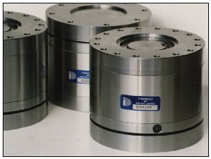
| | Figure 4. CyberDrive™ Coupling
|
|
The couplings are designed such they can fitted to the mill with minimum disruption to production and, in most cases, the complete installation can be completed within a few hours. If downtime is particularly critical, CyberDrive™ Couplings can be fitted to just one pair of roll shafts at any convenient break in production, as there can be no detrimental effect on the product or mill. There are no special maintenance requirements other than annual lubrication checks, and the couplings function completely automatically with no operator input.
Technical Benefits
In operation CyberDrive couplings allow each roll to rotate at a speed determined by the speed of the strip at the variable drive point. The couplings automatically compensate for the changes in drive point where some rolls will be providing significant drive while others will be providing little if any drive. No roll will be acting as a brake!
This action provides a substantial reduction in drive power with lower transmission stress and wear. Because the rolls are no longer fighting one another, roll pick-up and roll wear is reduced. With minimum conflict between roll and strip, material distortion and marking are virtually eliminated and lead to a significant improvement in product quality and consistency.
An additional benefit appears in smoother and quieter operation of the whole mill leading to significant reduction in overall noise levels from motors, gears, and other transmission components.
Following a five year investigation of tube mill accident reports, a Directive has been issued by the UK's Department of Health & Safety which refers to the CyberDrive™ concept as "a contributory factor in the reduction of accidents in mills by eliminating the need to remove pick-up marks whilst the mill is running".
Financial Benefits
All the Technical Benefits combine to furnish a commercial advantage with product having better appearance improved quality and greater consistency. Specific Case Studies have shown a reduction in drive power with a saving in energy costs of almost 50%, a decrease in roll and transmission wear with savings of up to 60% and, with less marking and greater consistency, scrap product reduced by more than 70%.
In most installations, the cost of the CyberDrive™ installation has been recovered within twelve months. Given the system's life expectancy of around 20 years, with no further replacement or additional running costs, savings can be expected year after year.
Further information can be obtained from:
Doltec Limited
- Addr: Rigg Lane,
Trent,
Sherborne,
Dorset. DT9 4SS ,
UK
- Tel: ++44 1935 851 034
- Fax: ++44 1935 851 311
- WWW: http://www.doltec.com
- Email.
- Contact: Keith Barraclough
|