Continuous, automatic processing of heavy-wall round tubing
By Jim Dalton, Bardons & Oliver, Inc., USA
Fabrication of parts from heavy-wall tubing typically has been done at several different stations within a job shop by operators who move the cut lengths from station to station manually. Operators might saw the tubing at one station, move it to another station to be double-chucked on a lathe, and then remove the part, clean it and gauge it. Depending on the length of the parts and the thickness of the wall, this can be a very labor-intensive process.
Manually transporting material from station to station is an industry standard for all kinds of jobs, especially for low-volume jobs in which high production capability is neither a requirement nor a cost-effective capital expense.
However, automated equipment has become more flexible to meet the need for short runs. Timing is good because many companies now face continuing pressure from large customers to provide value-added services, which often means providing more part processing capability.
One option for the flexible production of tubular parts - - axle housings, air and hydraulic cylinders, steering parts, and transmission parts, for example - - is to use an automatic system that will produce a continuous stream of parts from mill-length tubing.
Setup and Use
Tube fabricators who want continuous square cutting and chamfering of heavy-wall round tubing up to 0.750 inch thick must pay close attention to the raw material as it moves through cutoff and initial machining to the secondary operations performed that may be required.
Here's one approach a tube supplier used to provide value added service to its customers. This automatic system design incorporates stations for three processes:
- Magazine loader table for incoming tubes
- Cutoff lathe for close tolerance square cutting
- Secondary operations station used for chamfering, boring, cleaning, gauging, and unloading
The loading table is capable of handling mill length tubing--bundles of tubing from 13 to 30 feet in length and from one inch to seven inches in diameter. Wall thickness typically ranges from 0.125 to .750 inch. Mill lengths are heavy, requiring a sturdy magazine type loading table with components designed to prevent marring of the tube's exterior finish. The table can be integrated with a standard, programmable-logic-controlled, through-hole, cut-off lathe.
The Process
The sequence of operations with an automatic system is linear and simultaneous and is designed to run with minimal operator intervention.
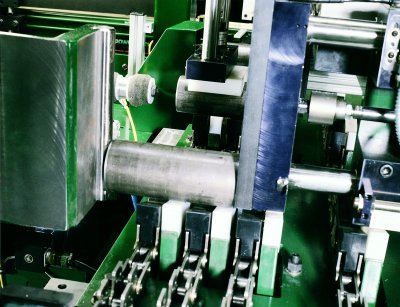
Beginning with the automatic feeding of the tubing through the collet (see Figure 1), the following is the sequence of operations from raw stock to finished part:
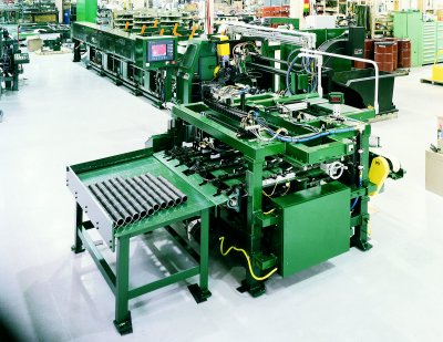
| |
Cut-Off Lathe with a secondary operations
station in the foreground
|
|
- Each new tube is lifted off the magazine storage rack and automatically pushed into the spindle with an encoder controlled pusher head. The encoder allows the tube to be pushed forward through the spindle to a pre-programmed end crop or trim cut position.
- The tube leading edge is trimmed by the cut-off slides equipped with carbide insert-type cutting tools. The OD and ID are chamfered by different slides also equipped with carbide insert tooling.
- The pusher then advances the tube to a preprogrammed part length stop.
- Cutoff begins with two carbide cutoff tools. The machine is equipped with automatic, selectable, interrupted cutting for low-carbon steel. Steel with a carbon content many times produces long stringy chips which are difficult to remove, stop automatic handling of the part and are a hazard to the operator. When selecting proper speeds and feeds, the operator may select "interrupted cutting" which is a programmed routine that feeds the cutting tool forward a set distance, then backs off and feeds again, breaking the chip into smaller, more controlled chips.
- The leading and trailing OD and leading end ID of the next part are chamfered simultaneously by separate slides equipped with carbide tooling.
- The part then is unloaded automatically to a belt conveyor for transfer.
- Cut parts are swept from the belt conveyor onto a chain conveyor for secondary operations. Remnant ends are ejected automatically and swept into a scrap bin.
The secondary operations station can be configured in a number of ways. For example, this application requires three operations:
- Chamfer of trailing edge ID. Facing could be also done for closer part tolerance length.
- Blow-off and cleaning of part. In this step, an air stream blows chips out of the part ID and a cylinder-mounted sponge rubber swab automatically cleans the length of the ID of chips and coolant residue.
- Post-process gauging is done by an electronic scale to ensure that parts meet dimensional length specifications.
The finished parts exit from the chain conveyor onto a gravity unload table
A mist coolant, as opposed to a flood coolant, can be used while cutting parts to reduce coolant contamination and the need for extensive part cleaning at the end of the process.
The complete system is designed to minimize part handling by an operator and keep the manufacturing of the part in a continuous flow with minimum floor space requirements.
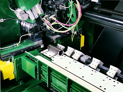
| |
The cut off part unloads to a conveyor to the secondary operations
station.
|
|
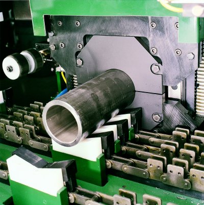
| |
The back of the part is chamfered on the ID
|
|
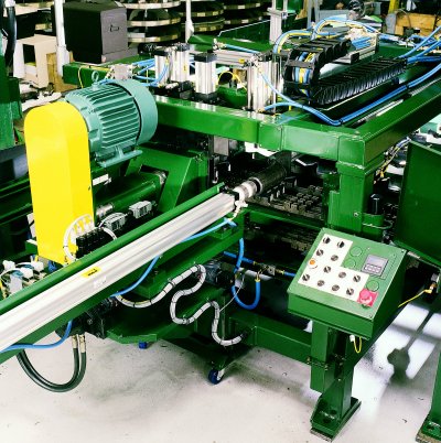
| |
A swab cleans the inside of the finished part
|
|
| |
Post process gauging assures each part meets requirements
|
|
Integrated Solutions
Whether or not an automated system is right for your situation depends on a number of factors …
- Are you able to double or triple your output quickly? Will you need to?
- Are you able to get enough qualified people?
- Can you changeover from one part to another at the push of a button? Will you need to?
- Do you have the floor space for expansion?
- Are your customers demanding you do more value-added services?
- Is your product quality consistent?
- Is your reject rate as low as you would like?
- Can you afford to risk accidents cause by fatigue from manually handling heavy parts?
An automated system will save floor space. Many times an operator can run two or more systems, saving on labor costs. Flexibility and productivity are maximized. Part quality and consistency will be enhanced. In today's environment of outsourcing, this could be what your customers will come to expect of you.
In continuous automatic processing of parts from tubing, close consideration must be given to the integration of material handling capabilities with the actual processing operations. The system must fit together seamlessly, with electricals, actuators and controls working in concert.
When shopping for components separately, a tube fabricator assumes the burden of making the system work. This approach may save some money, but with this approach comes the risk of things not fitting together or working together as planned. When buying separately, it becomes the buyer's responsibility to make it work. In any case, using two or more key suppliers on an integrated system makes it more difficult to resolve system problems. Sole souring puts the burden squarely on the system provider, where it belongs.
Jim Dalton is Vice President of Bardons & Oliver, Inc., 5800 Harper Road, Solon, OH 44139; Phone 440-498-5800; Fax 440-498-2001; E-Mail info@bardonsoliver.com; Web Site wwww.bardonsoliver.com.). Bardons & Oliver, Inc is
a 100-year old manufacturer of cut-off lathes, turning machines and integrated systems.
Bardons & Oliver, Inc
- Addr: 5800 Harper Road, Solon, OH 44139, USA
- Tel: 440-498-5800
- Fax: 440-498-2001
- WWW: http://wwww.bardonsoliver.com/
- Email:
- Contact: Jim Dalton
|