State of the art CNC tube bending
by Peter Chapman
Addison Tube Forming Ltd, UK

Peter Chapman
|
About author: Peter Chapman is Sales Director for Addison Tube Forming Ltd. and he has lifetime experience in machine tools. This includes conventional and dedicated tools as well as CNC based systems. The last 12 years he has been focusing Addison's products and applications worldwide.
State of the art CNC tube bending
The development of machines to manipulate and inspect tubular components has been dramatic over the last two decades, primarily due to the introduction of NC and CNC systems. Today it can be said that the industry offers systems and machinery the equal in level of sophistication of any on the market.
Systems for Tube Bending
There are many different methods of bending (Figure 1). However, it is universally accepted that the best method of producing good quality complex tubular components is draw bending. Most CNC bending machines use this system, and some models offer the options of 'compression bending' or 'boost bending'.

Figure 1. Various Bending Models
|
Component Data
A requirement before beginning the manufacture of any components is a drawing with the sizes to which it must be made, or a sample (Figure 2).
There are two basic methods of dimensioning: XYZ (Cartesian) co-ordinates, and YBC (Y = length between bends, B = rotation between bends, C = angle of bend). This is also referred to as LRA (Length-Rotation-Angle) and comprises the information required by the bending machine. Centre line radius, tube diameter, tube wall thickness, and tube material also must be established prior to manufacture.

Figure 2. A drawing with sizes or a sample needs to be made first
|
Computer controlled machines normally accept data supplied by either method and can automatically convert from one to the other. From a sample the modern inspection machine can produce a bending program and drawing of the component. (This will be discussed below.)
Tooling
Selecting the correct tooling to suit the many and various bending requirements is a matter for separate discussion. Figures 3 and 3a show a basic standard tooling configuration for use with a mandrel. The decision whether to use a mandrel, wiper die, compound tooling, heated tooling, etc. is dependent upon the quality of bend to be achieved, material to be used, and the many other factors which make tooling such an important item in the consideration of bending machines. 'Quality tooling is good economics'.
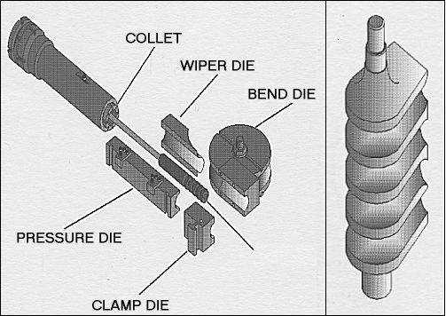
Figure 3 and 3a. Standard tooling configurations
|
Today's Standard CNC Bending Machine Today
To produce a program the information can be input in either XYZ or YBC data. Figures 4 and 5 show, respectively, a current Addison bender and its related control screen. Figures 6 and 7 are two of the many pages available on that screen.
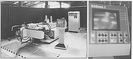
Figure 4 and 4a. Addison bender and control screen
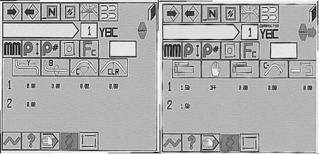
Figure 6 and 7. Screen captures from the controls
|
In programming it is possible to input considerable additional information including bend radius, tooling data, and data relating to other features that may be included on the machine.
Simplicity of Setup
There are many advantages to using CNC machines, among them speed, dependability, reliability, flexibility, and quality. Additionally, any one standard or advanced feature of the unit may well dictate the purchase. However, it should be possible to justify a standard CNC machine on the basis of simplicity of setup. The CNC is simple to program. Programs are easily modified. It is easy to recall successful programs from the memory and a simple matter to produce a different component very quickly to a reliable quality.
This gives the flexibility that industry requires and may enable even the smallest companies to justify the purchase of a CNC machine as against a manual-type unit.
Springback and Stretch
Once a program has been created it becomes necessary to consider the problems of springback and stretch, which can be compensated for in the following ways:
- Produce a component and measure it using the theoretical program. Add on the number of degrees of springback to each bend and compensate 'Y'dimensions to maintain end-to-end lengths. This exercise will be repeated several times before a good component is produced;
- Use a CNC control which has a standard springback feature. This requires a sample of the material to be bent to 20� and 120�. The measured results are then input into the control which will automatically compensate for any bend angles and Y dimensions in the program (Figure 8).
- Repeat the previous step, but measure on an Addison Addata Plus or AddiScan inspection machine and download the information automatically from the inspection machine to the bander.
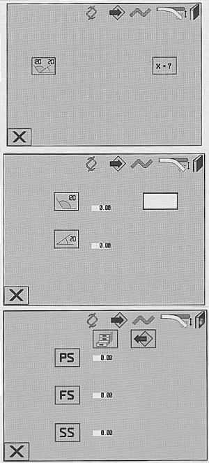
Figure 8. CNC controlled handling of
springback compensation
|
When the compensated program has been established the machine can be run to produce components to the same quality, consistently.
Other features available include full diagnostics capability, enabling operators and maintenance personnel to identify faults quickly and to manually operate each function from the control (Figure 9).
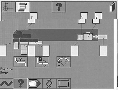
Figure 9. Full diagnostics and manual operation
|
Advanced Machine Software
The Addison CNC has the capability of controlling the most sophisticated manufacturing cell. That includes a multi-axis bending head (7/8 axis) linked to full automation (both loading and offloading), and DNC communication with other benders, inspection machines, and an IBM PC.
These features can be accessed from the control along with other functions such as 'hitch feeding', empty bending, recapture, printer output, reverse image, production monitoring, BC/IFZ, boost bending, and function code facility (Figure 10).

Figure 10. Advanced software features
|
The control has been designed specifically to meet the needs of bending machines: it is not an adaptation of a standard CNC system. It uses the latest technology and offers a simple-to-use operator touch screen.
Sophistication in a Bending Machine
Clearly even simple CNC machines are very sophisticated. Technology is producing more and more complex machines to meet a variety of needs, but the requirement for faster tooling setups has been one of the biggest challenges. Machines are available that automatically change the machine settings during tooling changeover The program can automatically change centre line radius, speed, and position of the follower slide, etc. Each of these functions essentially becomes an additional axis (Figure 11) which must justify its additional cost with a savings in setup time.

Figure 11. Faster set-ups must justify additional costs with a savings in setup time
|
Machines are also available with multiple "stacks" of tooling. These enable different bend radii to be automatically produced on one component, or for compound bends to be produced. The most complex of these machines also includes a boost facility for the production of 1 x diameter bend radii (Figure 12).
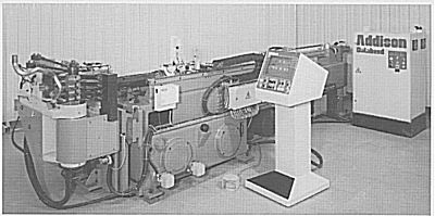
Figure 12. Multiple stacks of tooling - different radii automatically

Figure 12 b. "Stack" of multiple tooling
|
Automation
As machines become more complex and expensive, it is important that their production capability be maximised. Accordingly, many machines sold today are fully automated. It is relatively simple to automate the loading of machines for both empty and mandrel bending. Since, generally speaking, the only variables that have to be adjusted are diameter and length, side loaders and front loaders are standard items. Some 99 per cent of tubes to be loaded start off as straight tubes and can be de-bundled automatically into the machine loader.
However, the unloading of bent tubes entails some problems. Therefore the systems offered generally have to be robot-type, unless the components are of a very simple shape or produced in such volume that a dedicated solution can be designed. The sophistication of the Addison machine control ensures that the most complex robotic pick-and-place solution can be integrated with the machine (Figure 13).
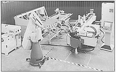
Figure 13. Pick-and-place with robots
|
In short, automation is a matter of studying all the various handling applications required and justifying the cost of the handling system needed.
Inspection Machines
There are many different types of inspection machine available for checking bent tube configurations. Some are based upon the three-coordinate measuring system with Renishaw-type touch probes, some with lasers, others with cameras. Possibly the simplest and most widely used is the articulated arm fitted with encoders, which measures the straights of a configuration and, by means of the vectors, automatically computes overall tube measurements. Arguably it was the introduction of this Addata type measuring system that led to the tremendous popularity of CNC bending machines.
The Addata Plus (Figure 14) has proven to be and still is a vital product in tubular component inspection for two main reasons:for two main reasons:
- its much more accurate measuring arm (five digital encoders) fitted with a noncontact probe;
- an IBM-compatible computer integrated into the machine, offering new software functions including full-colour screen for graphic representation of the component measured.

Figure 14. Addata Plus inspection machine
|
Previous models of this type of machine used probes that came into physical contact with the tube specimen. This can produce spurious data due to forces generated when the probe is positioned, commonly causing deflection or movement of the components or preventing a good contact. In addition, the need to rigidly clamp the sample in order to facilitate the contact measurement process can, in itself, create distortion, particularly on tubes of only nominal dimensions or with a thin wall.
In operation the sample to be measured is placed upon the inspection table, with the use of supports where necessary, and the noncontact probe applied to its length. Readings are taken at either end of the sample and at two points on each straight section between bends.
The measuring sequence can be carried out by an operator using just one hand, the probe automatically programming itself to receive the next measurement without the need to reset manually. The process produces different sound tones at each step of the operation,highlighting the next action required and indicating when measurements are in error or require to be repeated.
Having measured a component one can use the information to either:
- check against existing theoretical components in the memory. A printout as well as a graphic representation of errors can be produced based upon "hard point" or "best fit" inspection methods (Figure 15);
- use data to generate bending programs, and download direct to the bending machine;
- use the machine to re-design the component to suit special requirements;
- form part of an SPC procedure; or,
- download information to the bending machine to keep the component constantly within tolerance.
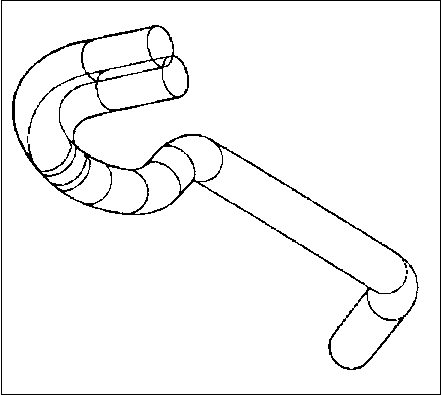
Figure 15. Graphical representations allows easy re-design
|
The machine can be used for many applications not previously considered on an inspection machine. For example, data can be input manually via the touch screen or a conventional keyboard, and the program produced in either XYZ or YBC format. The system can then produce a true three-dimensional (3-D) representation of any tube shape and display this on its integral 13-in. EGA colour monitor. The image can be rotated to permit all aspects of its form to be examined, thus enabling designers, programmers, and planning engineers to see the problems of distance between bends, etc. without having to manufacture a component. These graphics can be printed out with the coordinate data and inspection data as follows:
MASTER  / XYZ:

Number of Points = 7          Number of Straights = 6

Point         X           Y           Z        Radius
  1        -527.9      -983.1       215.1          -
------------------------------------------------------
  2        -520.1      -779.8       233.5       120.0
------------------------------------------------------
  3        -372.1      -786.3       154.9       120.0
------------------------------------------------------
  4        -227.8      -792.2       161.7       120.0
------------------------------------------------------
  5        -132.0      -802.6       230.2       120.0
------------------------------------------------------
  6        -487.6      -722.7       238.6       120.0
------------------------------------------------------
  7        -559.0      -596.4       221.9         -
------------------------------------------------------
End to End Length = 1191.3


 MASTER  / YBC:

Number of Points = 5          Number of Straights = 6

Point         Y           B           C        Radius
  1          78.5         0.0        92.7      120.0
------------------------------------------------------
  2           9.0       -94.8        30.6      120.0
------------------------------------------------------
  3          76.3         6.1        32.9      120.0
------------------------------------------------------
  4          42.8      -164.2        36.9      120.0
------------------------------------------------------
  5         539.1        62.1        41.7      120.0
------------------------------------------------------
            123.5
------------------------------------------------------
Developed Length = 1361.0


 Corrected YBC Data:

Number of Bends = 5          Number of Straights = 6

Point         Y           B           C        Radius
  1          78.5         0.0        92.7      120.0
------------------------------------------------------
  2           9.0       -94.8        30.6      120.0
------------------------------------------------------
  3          76.3         6.1        32.9      120.0
------------------------------------------------------
  4          42.8      -164.2        36.9      120.0
------------------------------------------------------
  5         539.1        62.1        41.7      120.0
------------------------------------------------------
            123.5
------------------------------------------------------


Part Number: 888      Unit Mode: Metric (millimeters)

Tube Inspection Report

Number of Straights = 6
Inspection Method : HARD-POINT METHOD
Hard-point Inspection Reference Points:

Point     Straight     Type       X         Y        Z
  1          6          T1      319.7     972.7   -323.2
------------------------------------------------------
  2          6          T2      412.1   1054.5    -327.1
------------------------------------------------------
  3          5          T2      278.7     899.2   -308.4
------------------------------------------------------
  4          5          T1      198.5     389.9   -151.2
------------------------------------------------------
INSPECTION VARIABLES:
1. Fit Tolerance (Best-Fit)............ 0.1
2. A-End Bias Factor (1-20)............ 3.0
3. B-End Bias Factor (1-20)............ 3.0
4. Third Straight Bias Factor (1-10)... 1.0
5. Max Iterations (Best-Fit)........... 20.0
6. Qualification Envelope Tolerance.... 1.0

NOTE:  These dimensions are related to the tube centerline
       measurements and MAY be used for inspection
       purposes:

Ends Statistics:

   End          Length        Angle        Offset
    A           -5.8***        1.3         34.6***
--------------------------------------------------
    B            0.1           0.0          1.2***
--------------------------------------------------
End to End Length Offset = 13.1

Critical Point Statistics:


   Straight       Tangent Point 1       Mid Point       Tangent Point 2
      1               34.6***            34.5***            34.5***
-----------------------------------------------------------------------
      2                6.4***             5.8***             5.3***
-----------------------------------------------------------------------
      3                3.3***             3.0***             2.7***
-----------------------------------------------------------------------
      4                1.5***             1.1***             0.7
-----------------------------------------------------------------------
      5                0.0                0.1                0.2
-----------------------------------------------------------------------
      6                1.2***             1.2***             1.2***
-----------------------------------------------------------------------
|
Different sizes of probe can be fitted and previously problematic sizes, angles, and configurations measured quickly and accurately.
Vision Technology for Tube Inspection
The AddiScan (Figure 16) from Addison Tube Forming Ltd is a major breakthrough in tubular component inspection. It uses a camera-based system for these reasons:
- The tube can be presented in any position without fixing;
- Operation is fully automatic;
- Repeatability is increased by eliminating manual probing;
- Incorporation into automated bending cells gives regular monitoring of quality and correction of bending programs.
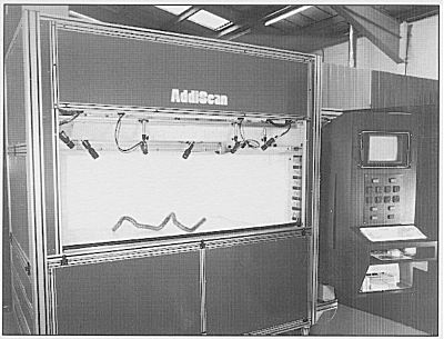
Figure 17. Camera based AddiScan inspector
|
The AddiScan is essentially a large light box, used to uniformly illuminate a tube from all six sides. The design of the lighting minimises reflections and shadows. Sheets of perspex material are used to diffuse the light, giving a high light level and thus a large depth of field for the imaging system, keeping the tube in focus over the entire measurement volume.
Six video cameras are positioned around the top of the rig and used to grab images of the bent tube.
Prior to any measurement the AddiScan first has to be calibrated. This is carried out by means of a target mounted in the base of the system and consisting of a large number of highly accurate measured features (Figure 18). This procedure needs to be done only occasionally, perhaps once a day.
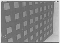
Figure 18. The importance of calibration
|
For measurement a component is placed anywhere inside the light box and the door closed. The name, part number, and bend radius are input into the computer. Each camera from its individual direction collects a snapshot of the component (Figure 19). The necessary visual information having been captured, the door can then be opened and the component removed whilst its geometry is being automatically calculated. The geometry data is available in several different formats, including YBC and XYZ coordinates and 3-D shaded graphic models.

Figure 19. AddiScan in action. Snapshots are taken
|
In addition to measuring a virgin component the system is able to compare two similar parts. For example, with a component which has not been compensated against springback the system can transfer the correct data to the bending machine, or produce a variety of data representations which can be printed out as text reports or graphics (Figure 20) below.
Ends Statistics:
Date       : 08/19/97
Time       : 16:28:23
Name       : No name
Straights  : 6
Fit        : Best
Form       : Short

End Points:

   End          Length        Angle        Offset
    A            0.198        0.011        0.055
--------------------------------------------------
    B            0.012         0.056       0.082
--------------------------------------------------
End to End Length Offset = -0.014

Critical Point Offsets:


   Straight       Tangent Point 1       Mid Point       Tangent Point 2
      1               0.055             0.063              0.070
-------------------------------------------------------------------
      2               0.040             0.057              0.078
-------------------------------------------------------------------
      3               0.109             0.173              0.237
-------------------------------------------------------------------
      4               0.251             0.249              0.423
-------------------------------------------------------------------
      5               0.390             0.296              0.203
-------------------------------------------------------------------
      6               0.153             0.117              0.082
-------------------------------------------------------------------
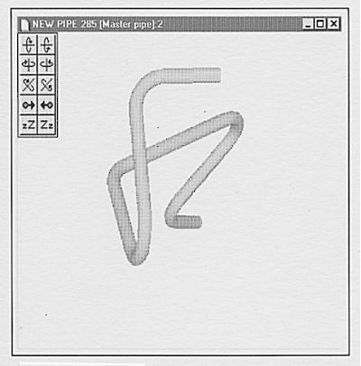
Figure 20. Graphical view from measured tube
|
With very little operator involvement (component placement, pressing a button to close and open the door), the margins of error have been narrowed to the minimum to ensure maximum profitability.
LAN/DNC
With the development of CNC machines with multi-axis controls, automation systems, and inspection machines, it was inevitable that systems for the transfer of data among machines would be next in line.
DNC has been around for several years in the machine tool industry. The basic concept is to provide a means of distributing manufacturing instructions to production machines without having to use hard copy.
Addison"s objective was to provide a Local Area Network (LAN) to connect bending and measuring machines, enabling data to be passed around freely, and further to provide a link with computer-aided design systems. The link to CAD presents numerous problems because many different formats and protocols are in use throughout the industry. Our solution was to interpose an IBM PC into the LAN to provide a means of interfacing with the CAD computer. This PC was subsequently enhanced to provide further facilities such as data edit and post-processing. It also served to isolate the CAD from the network and give added data security to the main-frame system (Figure 21).
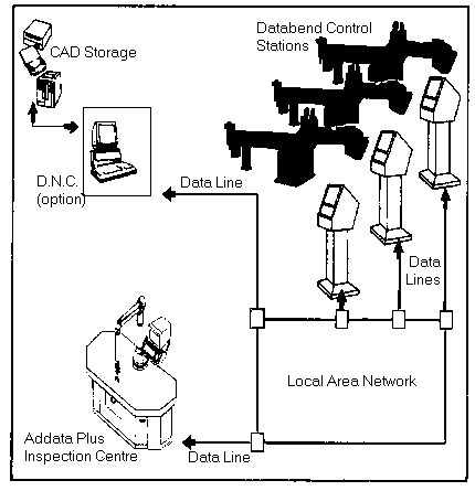
Figure 21. Addison's Databenders with LAN configuration
|
This arrangement is not often required today because the Addison Addata Plus has its own PC and can be used in the LAN to store and distribute programs along with tool management data.
A full DNC system offers the benefit of being able to distribute programs without the need of paper media, thus reducing human error and improving setup times. At the machine an operator can request programs and tooling information from the PC in the network (or Internet) . Properly equipped with the correct software the PC becomes a production control tool, distributing work orders to bending units and recalling inspection data after production (Figure 22). The DNC/LAN package complements the many advances made in pipe bending and measuring.
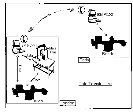
Figure 22. Addison's Databenders with DNC/LAN package
|
Further information concerning the article above can be get from:
Addison Tube Forming Limited
Attn: Peter Chapman
188 Bradkirk Place, Walton Summit Centre, Bamber Bridge, Preston, Lancashire, Pr5 8aj, UK
Tel. +44 (1772) 334511
Fax: +44 (1772) 323227
WWW. http://www.atf.co.uk
Email.
|